
- Vermont Castings 820, 2822, 2823, 2825, 2827, 2828

23
Vermont Castings Jefferson Direct Vent/Natural Vent Gas Heater
20002191
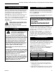
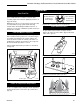
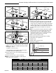
90°
Left Burner Leg
Injector Shoulder
Fig. 41 Be sure to maintain 90° angle at left burner leg.
ST353
Complete the Assembly
• Open the swiveling latches (cams) on the top left
and right corners of the glass frame.
• Position the glass and frame against the firebox by
placing the bottom edge on the brackets on the
bottom face of the firebox.
• Swing the assembly against the firebox, and close
the latches firmly against the pins protruding from
the firebox top.
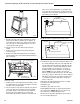
Install ON/OFF Switch
The switch assembly parts are found in the parts bag.
1. Attach switch assembly to left rear side of stove
shroud using two screws and existing holes in
shroud. (Fig. 42)
2. Run wires down back of stove, under bottom of rear
shroud to valve.
3. Attach wires to valve terminals. (Fig. 43)
Switch
Assembly
Screws
Existing
Holes
ST315
Fig. 42 Attach switch assembly to rear shroud.
PILOT
ADJ
TP
TH
TPTH
ST228
Fig. 43 Attach switch wires to valve.
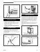
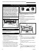
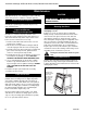
Install the Stove Front
The Front Plate attaches to the stove by four steel tabs
that engage with corresponding cast ribs on the sides
and bottom of the stove body. Position the Front about
3” down from stove top and lift the plate to engage the
upper tabs behind the adjacent ribs on the sides. (Fig.
44) Then lower the plate into position, so that the
lower tabs engage with the corresponding ribs at the
bottom. (Fig. 45)
When properly installed, the bottom of the Stove Front
cannot be pulled away from the sides without also
lifting it.
Control Door
Lower Tabs Engage
Ribs in Bottom
ST229
Fig. 44 Install Stove Front.
3”
Upper Tabs
Stove Side
Side Rib
Front Tab
Stove Front
ST279
Fig. 45 Engage with side ribs.