INSTALLER / CONSUMER SAFETY INFORMATION PLEASE READ THIS MANUAL BEFORE INSTALLING AND USING APPLIANCE. Jefferson ® WARNING! IF THE INFORMATION IN THIS MANUAL IS NOT FOLLOWED EXACTLY, A FIRE OR EXPLOSION MAY RESULT CAUSING PROPERTY DAMAGE, PERSONAL INJURY OR LOSS OF LIFE. Direct Vent/Natural Vent Gas Heater Model JDV: 2820, 2822, 2823, 2825, 2827, 2828 FOR YOUR SAFETY Installation and service must be performed by a qualified installer, service agency or the gas suppler.
Vermont Castings Jefferson Direct Vent/Natural Vent Gas Heater Table Of Contents PLEASE READ THE INSTALLATION & OPERATING INSTRUCTIONS BEFORE USING APPLIANCE. Thank you and congratulations on your purchase of a Vermont Castings stove. IMPORTANT: Read all instructions and warnings carefully before starting installation. Failure to follow these instructions may result in a possible fire hazard and will void the warranty. Installation & Operating Instructions ..................................................
Vermont Castings Jefferson Direct Vent/Natural Vent Gas Heater Installation & Operating Instructions The Jefferson Direct Vent/Natural Vent Room Heater, Model Nos. 2820, 2822, 2823, 2825, 2827 and 2828, is a vented gas appliance listed to the ANSI Standard Z21.88b2001 and CSA-2.33b-2001 for Vented Room Heaters, and CSA 2.17-M91, Gas-Fired Appliances For Use at High Altitudes.
Vermont Castings Jefferson Direct Vent/Natural Vent Gas Heater Jefferson Direct Vent/ Natural Vent Stove Dimensions 28¹⁄₂" C L Valve 3" Inlet 14¹⁄₂" 24" 8" See Page 6 for Flue Collar Centerline Dimensions. ST206 Fig. 1 Jefferson dimensions. Attention The Jefferson stove is shipped from the factory as a Direct Vent Gas Heater. This heater may be converted into a Natural Vent unit in the field.
Vermont Castings Jefferson Direct Vent/Natural Vent Gas Heater Installation Requirements The installation must conform with local codes or, in the absence of local codes, with the National Fuel Gas Code, ANSI Z223.1 - latest edition. (EXCEPTION: Do not derate this appliance for altitude. Maintain the manifold pressure at 3.5 inches w.c. for Natural Gas, and 10 inches w.c. for Propane). Direct Vent System Only A D In Canada, installation must be in accordance with the current CSA B-149.
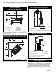
Vermont Castings Jefferson Direct Vent/Natural Vent Gas Heater Parallel Installation: Minimum Clearance and Flue Centerline, Direct Vent and Natural Vent Wall Thimble Centerline from Floor Direct Vent Only C L C A D A C L B ST131a Stove Clearances A: 4” (102mm) B: 4” (102mm) C: 14¹⁄₂” (369mm) D: 9” (229mm) Pipe Centerlines ST128a A Effective Minimum Wall Thimble 58 ¹/₄” (1480mm)(CFM Majestic Pipe) Centerline 54¹⁄₄” (1378mm) (Simpson DuraVent Pipe) Fig. 5 Minimum wall thimble centerline. Fig.
Vermont Castings Jefferson Direct Vent/Natural Vent Gas Heater Horizontal Termination Direct Vent ONLY Gas Specifications Model Fuel Gas Control Max. Input BTU/h JDVRN JDVRP Nat Prop Millivolt Millivolt 28,000 28,000 Min. Input BTU/h 20,000 19,000 Weight: Fully assembled; 350 lbs. The vent must rise vertically a minimum of 24” (610mm) off the top of the unit, before the first elbow. The horizontal run may extend up to 20’ (6m) and include a vertical rise of up to 40’ (12m). (Fig.
Vermont Castings Jefferson Direct Vent/Natural Vent Gas Heater Vertical Termination - Direct Vent ONLY Vent Termination Clearances A vertical vent system must terminate no less than 8' (2.44m) and no more than 40’ (12m) above the appliance flue collar. A 2¹⁄₄" restrictor plate (supplied) must be used, where specified, in all vertically terminated vent systems. (Refer to Figure 8) NOTE: The restrictor plate supplied with the vertical termination should be discarded.
Vermont Castings Jefferson Direct Vent/Natural Vent Gas Heater Vent Termination Clearances - Direct Vent ONLY Your stove is approved to be vented either through the side wall, or vertical through the roof. • Vermont Castings, Majestic Products does not require any opening for inspection of vent pipe. • Only Vermont Castings, Majestic Products and Simpson DuraVent venting components specifically approved and labelled for this stove may be used.
Vermont Castings Jefferson Direct Vent/Natural Vent Gas Heater General Venting Information - Termination Location INSIDE CORNER DETAIL G V H A D V N N E V B C V L B Fixed Closed Ope F B V Operable rab V le V Fixed Closed G V B B B V J X I A V VENT TERMINATION M G V K X V A X AIR SUPPLY INLET AREA WHERE TERMINAL IS NOT PERMITTED CFM145a Canadian Installations1 A = Clearance above grade, veranda, porch, deck, or balcony B = Clearance to window or door that may be opened
Vermont Castings Jefferson Direct Vent/Natural Vent Gas Heater Termination Clearances Termination clearances for buildings with combustible and noncombustible exteriors.
Vermont Castings Jefferson Direct Vent/Natural Vent Gas Heater Venting Requirements and Options Direct Vent ONLY Approved Vent System Components The Stardance Heater must be vented to the outdoors through an adjacent exterior wall or through the roof. The venting system must be comprised of the appropriate listed venting components specified on this page. These parts are available from DuraVent Corporation or your Vermont Castings Majestic Products Dealer.
Vermont Castings Jefferson Direct Vent/Natural Vent Gas Heater Assembly Procedures WARNING Failure to position the parts in accordance with these diagrams or failure to use only parts specifically approved for use with this heater may result in property damage or personal injury. This heater and components are heavy. Have help available for assembly. Tools Required • Phillips screwdriver (stub) • power drill • utility knife • reciprocating saw • metal drill bit: size 28 (.140”/3.
Vermont Castings Jefferson Direct Vent/Natural Vent Gas Heater 3. Attach the fan to the rear shroud by engaging the upper flange of the fan skirt under the lower edge of the shroud and secure the skirt with the four screws and one star washer provided. (Fig. 14) 4. The rheostat control switch attaches to the left side of the valve bracket at the front of the stove. • Remove the plug from the rheostat bracket.
Vermont Castings Jefferson Direct Vent/Natural Vent Gas Heater • Side Wall Terminations: Dry fit the inner elbow with the vertical inner vent and confirm the centerline alignment with the wall thimble opening. 4. Attach the Inner Vent Assembly to the stove. • Run a bead of sealant around the bottom end of the starter pipe and attach the assembly to the stove using three 1/4-20 x 3/8” Phillips screws provided in the parts bag. (Fig. 18) 5. Install the Outer Adapter Pipe.
Vermont Castings Jefferson Direct Vent/Natural Vent Gas Heater 12” (305mm) Max. Length Sleeve #8 Sheet Metal Screws ST356 Firestop ZCS103 Fig. 21 Simpson Dura-Vent - install outer adapter pipe. Side Wall Termination Assembly 1. Locate the vent opening on the wall. Refer to Figure 5, Page 6, to determine the opening centerline. It may be necessary to first position the stove and measure to find the hole location.
Vermont Castings Jefferson Direct Vent/Natural Vent Gas Heater 6. Seal and install the elbow using 3 sheet metal screws at each joint. 7. Measure, and cut if needed, the appropriate length of pipe section needed to make the connection through the wall. Include a 2” overlap; i.e. from the elbow to the outside wall face, about 2” or the distance required if installing a second 90° elbow. (Fig. 25) 8.
Vermont Castings Jefferson Direct Vent/Natural Vent Gas Heater Wall Screws and Anchors Snorkel Termination Cap Waterproof Seal Around Pipe Firestop 4” Clearance Gravel Drain Window Well ST218 This installation will require you to first determine the roof pitch and use the appropriate vent components. Refer to Figures 8 and 9 on pages 8 and 9. 1. Locate the final position of the stove, observing all clearances for both the vent and the stove. 2.
Vermont Castings Jefferson Direct Vent/Natural Vent Gas Heater 9. Install the storm collar and seal around the joints. (Fig. 31) 10. Add additional vent lengths to achieve the proper overall height. 11. Apply cement to the inner and outer termination collars and install the terminal cap. Decorative 7” Pipe 4” B-vent Pipe CFM Direct Vent System may be used after Draft Hood up to the ceiling.
Vermont Castings Jefferson Direct Vent/Natural Vent Gas Heater 1 3 2 NT ME CE Decorative Grate ST223 Fig. 34 Install the back, left and right logs. ST357 5 Fig. 33 Install draft hood adpater. Install the Log Set 1. Remove the logs from their packaging, and inspect each piece for damage. DO NOT INSTALL DAMAGED LOGS. 2. Install the rear log 1 by centering it side to side on the sheet metal shelf at the back of the firebox. (Fig. 34) 3.
Vermont Castings Jefferson Direct Vent/Natural Vent Gas Heater Connect the Gas Supply Line Burner Information Check the Rating Plate attached by a steel cable to the firebox, to confirm that you have the appropriate firebox for the type of fuel to be used. The Jefferson may be converted from one gas to another using the appropriate Fuel Conversion Kit listed on page 34. The appliance must only use the gas specified on the rating plate, unless converted using a Vermont Castings Fuel Conversion Kit.
Vermont Castings Jefferson Direct Vent/Natural Vent Gas Heater inlet to close from a minimum 1/2” opening to fully open. (Fig. 40) You may have to try more than once to find the correct air shutter opening for best results depending on your altitude. Air Shutter (Original Position) See Table 1 Burner ST229a Fig. 37 Remove stove front. 3. Pull the top edge of the glass and frame assembly away from the firebox, and lift it off its supports on the bottom of the firebox face.
Vermont Castings Jefferson Direct Vent/Natural Vent Gas Heater PILOT ADJ TPTH TP Left Burner Leg Injector Shoulder TH 90° ST228 Fig. 43 Attach switch wires to valve. Install the Stove Front ST353 Fig. 41 Be sure to maintain 90° angle at left burner leg. Complete the Assembly • • • Open the swiveling latches (cams) on the top left and right corners of the glass frame. Position the glass and frame against the firebox by placing the bottom edge on the brackets on the bottom face of the firebox.
Vermont Castings Jefferson Direct Vent/Natural Vent Gas Heater Thermostat Connection (optional) Use only a thermostat rated for 500 millivolts. Check the table below for the appropriate gauge thermostat wire to use for the length of lead required in your installation. Thermostat Wire / Gauge Maximum Run 18 20 feet 16 20 - 40 feet 14 up to 60 feet 1. Install the wall thermostat in the desired location and run the wires to the stove location. Terminate these leads with 1/4” female connectors. 2.
Vermont Castings Jefferson Direct Vent/Natural Vent Gas Heater Your First Fire Read these instructions carefully and familiarize yourself with the burner controls. Locate the pilot assembly, Figure 46. Follow the lighting instructions on Page 28 exactly. During the first fire, it is not unusual to smell some odor associated with new logs, paint and metal being heated. Odors should dissipate within an hour or so, however, you can open a window to provide fresh air to alleviate the condition.
Vermont Castings Jefferson Direct Vent/Natural Vent Gas Heater Lighting And Operating Instructions FOR YOUR SAFETY READ BEFORE LIGHTING WARNING:If you do not follow these instructions exactly, a fire or explosion may result causing property damage, personal injury or loss of life. A. This heater has a pilot which must be lit manually. When lighting the pilot follow these instructions exactly. B. BEFORE LIGHTING smell all around the heater area for gas.
Vermont Castings Jefferson Direct Vent/Natural Vent Gas Heater Troubleshooting / Honeywell #8420 Gas Control System NOTE: Before troubleshooting the gas control system, be sure the external gas shutoff is in the “ON” position. WARNING: REMOVE THE GLASS PANEL BEFORE PERFORMING ANY GAS CONTROL SERVICE WORK. SYMPTOM 1. Spark ignitor will not light 2. Pilot will not stay lit after carefully following the lighting instructions 3.
Vermont Castings Jefferson Direct Vent/Natural Vent Gas Heater Fuel Conversion Instructions WARNING! This conversion kit shall be installed by a qualified service agency in accordance with the manufacturer’s instructions and all applicable codes and requirements of the authority having jurisdiction. If the information in these instructions is not followed exactly, a fire, explosion or production of carbon monoxide may result causing property damage, personal injury or loss of life.
Vermont Castings Jefferson Direct Vent/Natural Vent Gas Heater Pilot Hood Pilot Orifice Pilot Bracket CO105a Fig. 54 Remove pilot hood. CO106b Index Tab Allen Wrench Fig. 57 Remove pilot orifice. Snap Ring CO106a Fig. 55 Remove pilot orifice. Pilot Hood Index Marks Pilot Bracket CO105 16.Replace burner. Slide the burner in at an angle with left side lower than the right side. Slide the left side onto the injectors, making sure the burner leg remains at a 90° angle to the base.
Vermont Castings Jefferson Direct Vent/Natural Vent Gas Heater Maintenance Your Jefferson Gas Heater will provide years of service with minimal upkeep. The following procedures will help ensure that you stove continues to function properly. Annual System Inspection CAUTION TURN THE PILOT OFF BEFORE PAINTING. ALLOW THE HEATER TO COOL COMPLETELY BEFORE PAINTING. Have the entire heater and venting system inspected annually by a qualified gas technician. Replace any worn or broken parts.
Vermont Castings Jefferson Direct Vent/Natural Vent Gas Heater Inspect the Vent System Annually Have the vent system inspected annually by a qualified technician. Shut off the main gas supply before inspecting the system. Both the inner exhaust pipe and the outer combustion supply pipe must be checked to confirm that they are unblocked and in good condition. ST208a Fig. 60 Release the latches to release the glass frame.
Vermont Castings Jefferson Direct Vent/Natural Vent Gas Heater Wiring Diagrams OFF BLK WHT Thermopile Black On/Off Switch Wiring TP/TH FAN POWER CORD ON BL Chassis Ground TP K GRN Black TH BL ST124b FAN JUNCTION BO X Thermopile Black BLK Thermostat (Optional) Optional Thermostat Wiring TP/TH K Strain Relief ON / OFF Rheostat TP Black TH Snapstat ST124c LK WHT NOTE: IF ANY OF THE ORIGINAL WIRE, AS SUPPLIED WITH THE APPLIANCE, MUST BE REPLACED, IT MUST BE REPLACED WITH TYPE SF
Vermont Castings Jefferson Direct Vent/Natural Vent Gas Heater 2 5a,b 4 1a 6 3 T EN M CE 1b 1c 7 8 10a,b 11b 9 12 13 15 11a 1e 14 O H 1d I L ON T OFF LO PI 16 18 TPTH TP 22 TH 17 19 PILOT ADJ 21 25 20 29 28 26 23 30 27 31 2191 Vermont Castings, Majestic Products reserves the right to make changes in design, materials, specifications, prices and discontinue colors and products at any time, without notice.
Vermont Castings Jefferson Direct Vent/Natural Vent Gas Heater Jefferson Direct Vent/Natural Vent Gas Heater (continued) Models 2820, 2822, 2823, 2825, 2827, 2828 Ref. 7. 8. 9. 10a. 10b. 11a. 12. Description Gasket, Glass - Med. Knit - RDV40 Glass, JDV Glass Frame Assembly - JDV Valve RN Honeywell VS8420E 2038 Valve RP Honeywell VS8420E 2020 Pilot Assembly 3Way N/DV RN 0.199.706 Pilot Assembly 3Way N/DV RP 0.199.703 Pilot, PSE - NA175 Pilot, PSE - LP175 Thermocouple 24” 13. 14. 15.
Vermont Castings Jefferson Direct Vent/Natural Vent Gas Heater Optional Accessories Fan Kits FK28 Fan The FK28 fan helps distribute heated air from within the firebox out into the room. The fan is controlled by a snapstat that turns power on and off as the firebox temperature rises above and falls below a preset temperature. A rheostat provides for variable fan speeds. Remote Controls The remote control allows you to turn the heater on or off from anywhere in the room.
LIMITED LIFETIME WARRANTY PRODUCT COVERED BY THIS WARRANTY All Vermont Castings gas stoves, gas inserts, and gas fireplaces, and all Majestic or Northern Flame brand gas fireplaces equipped with an Insta-Flame Ceramic Burner, or standard steel tube burner.