INSTALLER / CONSUMER SAFETY INFORMATION PLEASE READ THIS MANUAL BEFORE INSTALLING AND USING APPLIANCE. WARNING! IF THE INFORMATION IN THIS MANUAL IS NOT FOLLOWED EXACTLY, A FIRE OR EXPLOSION MAY RESULT CAUSING PROPERTY DAMAGE, PERSONAL INJURY OR LOSS OF LIFE. Radiance Natural Vent Gas Heater Model RNVOD: 3340 thru 3349, 3355, 3356 — Do not store or use gasoline or other flammable vapors and liquids in the vicinity of this or any other appliance.
Radiance Natural Vent Gas Heater Table of Contents PLEASE READ THE INSTALLATION & OPERATING INSTRUCTIONS BEFORE USING APPLIANCE. Thank you and congratulations on your purchase of a Vermont Castings stove. IMPORTANT: Read all instructions and warnings carefully before starting installation. Failure to follow these instructions may result in a possible fire hazard and will void the warranty. Installation & Operating Instructions Stove Dimensions ...............................................................
Radiance Natural Vent Gas Heater Installation & Operating Instructions The Radiance Natural Vent Room Heater, Model Nos. 3340 thru 3349, 3355, 3356 is a vented gas appliance listed to the ANSI Standard Z21.88b-2001 and CSA-2.33b-2001 for Vented Room Heaters, and CSA 2.17-M91, Gas-Fired Appliances For Use at High Altitudes. The installation of the Radiance Natural Vent Room Heater must conform with local codes, or in the absence of local codes, with National Fuel Gas Code, ANSI Z223.
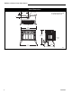
Radiance Natural Vent Gas Heater Stove Dimensions 4" Inner Dia. (100mm) 14⁷⁄₈" (378mm) CL See Page 5 for Flue Collar Centerline Dimensions. 4¹⁄₂" (114mm) 29³⁄₄" (756mm) RADIANCE 28" (711mm) Supply Inlet 5" (127mm) 31" (787mm) 9¹⁄₂" (241mm) 18¹⁄₄" (464mm) 4409 Fig. 1 Radiance dimensions.
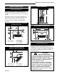
Radiance Natural Vent Gas Heater Ceiling Clearances Clearance Requirements Minimum Clearances to Combustible Materials Measure side clearances as shown in Figures 2 through 5 from the outer edge of the cast iron stove top. Measure rear clearances from the rear sheet metal shroud. 46" (1168mm) 74" (1880mm) The Radiance heater is approved for installation into an alcove constructed of combustible materials to the dimensions and clearances shown on this page.
Radiance Natural Vent Gas Heater Venting Requirements and Options Gas Specifications Model RNVODRN RNVODRP Fuel Gas Control Nat Millivolt Prop Millivolt Max. Min. Input Input BTU/h BTU/h 35,000 25,000 35,000 27,000 Weight: Fully assembled 350 lbs. Gas Inlet and Manifold Pressures Inlet Minimum Natural 5.5” w.c. LP (Propane) 11” w.c. Inlet Maximum 14” w.c. 14” w.c. Manifold Pressure 3.5” w.c. 10” w.c. Radiance Natural Vent Certified to: ANSI Z21.88b-2001 / CSA Z2.
Radiance Natural Vent Gas Heater Passing Through a Combustible Wall or Ceiling Complete the venting system installation according to the manufacturer’s instructions. Air Space as Required by Code Joists Ceiling Support 36 Vertical Run (in feet) (Measured from top of the unit before any elbow) An approved pass-through device is always required when a vent passes through a combustible wall or ceiling. Check with the maker of the vent system for the correct listed devices that are available.
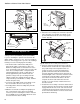
Radiance Natural Vent Gas Heater Assembly Procedures Tools Required • Phillips screwdriver (stub) • power drill • utility knife • reciprocating saw • metal drill bit: size 28 (.140"/3.5mm) CAUTION: To prevent valve tubing from being crushed or damaged, make sure to rest valve on wooden pallet. Unpack and Set Up the Stove The Radiance is shipped on its back. Cut the shipping straps and set stove upright.
Radiance Natural Vent Gas Heater 1. The fan kit includes a Blower Assembly and a Rheostat Assembly, connected by a cable. (Fig. 10) The Blower Assembly mounts to the bottom rear of the stove, and the Rheostat mounts to the left side of the valve. The assembly includes a 'snapstat' which automatically turns the fan On (or Off) above (or below) approximately 109˚F. The Rheostat also provides a range of fan speed settings from Off (which overrides the snapstat function) to High.
Radiance Natural Vent Gas Heater Rear Shroud Cover Plate A Rear Shroud Assembly A ST713 ST371 Fig. 13 Attach rear shroud cover plate to the rear shroud. Fig. 15 Remove rear shroud. 5. Attach the fan assembly to the fan bracket provided in the finish bag. Use the #10 sheet metal screws provided with fan kit. Do not remove finger guard screws. (Fig. 16) Snapstat Wire Rheostat Rheostat Wire Rheostat Retaining Collar Rheostat Knob Fan Bracket ST347a Fig. 14 Attach the fan rheostat.
Radiance Natural Vent Gas Heater Snapstat Bracket Snapstat Left Air Duct Snapstat Module Pinch Grommet to Remove ST671 Fig. 19 Install the snapstat and connect the extension wire terminals. View is with top removed, however, access is available through the rear when installing fan befoe gas line connection. ST670 Fig. 17 Remove the snapstat and grommet from the bracket and insert the grommet into the inner shroud. Outer Shroud Slot Inner Shroud Slot Retaining Nut Control Knob ST347a Fig.
Radiance Natural Vent Gas Heater Venting System Assembly Adjust the leg levelers as needed. They should not extend any further from the leg than necessary. The venting collar is on the sheet metal draft hood/heat exchanger assembly, over the firebox. Use a B-vent adapter, from the same maker as the rest of the B-vent components, to join the first section of venting to the draft hood. do not need to be fastened at each joint, other than slip sections.
Radiance Natural Vent Gas Heater Connect the Gas Supply Line Check the Rating Plate attached by a steel cable to the firebox, to confirm that you have the appropriate firebox for the type of fuel to be used. The Radiance may be converted from one gas to another using the appropriate Fuel Conversion Kit listed on Page 26. CAUTION This appliance should only be connected by a qualified gas technician. Test to confirm manifold pressures as specified below.
Radiance Natural Vent Gas Heater Install Rear Bracket and Log Set PILOT ADJ TPTH 1. Remove the logs from their packaging, and inspect each piece for damage. DO NOT INSTALL DAMAGED LOGS. TP TH Rear Log Bracket ST228 Fig. 26 Attach switch wires to valve. Thermostat Connection (optional) Use only a thermostat rated for 500 - 750 millivolts. Check the table below for the appropriate gauge thermostat wire to use for the length of lead required in your installation.
Radiance Natural Vent Gas Heater Right Log Left Rear Log Right Rear Log Top View Right Rear Log Left Rear Log Decorative Grate Lava Rock may be placed in this area NOTE: Right log is not shown in this view. Left Bracket Decorative Grate LG160 Fig. 30 Place lava rock on top of burner just behind decorative grate. Right Bracket LG156 Fig. 28 Install the left and right rear logs and the right log. Log rests on decorative grate Lava Rock LG155 Fig. 29 Completed log installation.
Radiance Natural Vent Gas Heater Operation Operable Doors The Radiance is shipped with the operable door front. The stove may be operated with the doors either open or closed. To open the front doors, insert the handle into the door latch stub and turn it to the right and up. (Fig. 31) When not in use, the handle may be stored in the handle holder on the right side of the rear shroud. (Fig. 32) Pilot Assembly ST476 Fig. 33 Pilot Assembly location.
Radiance Natural Vent Gas Heater Lighting and Operating Instructions FOR YOUR SAFETY READ BEFORE LIGHTING WARNING:If you do not follow these instructions exactly, a fire or explosion may result causing property damage, personal injury or loss of life. A. This heater has a pilot which must be lit manually. When lighting the pilot follow these instructions exactly. B. BEFORE LIGHTING smell all around the heater area for gas.
Radiance Natural Vent Gas Heater Troubleshooting / Honeywell #8420 Gas Control System NOTE: Before troubleshooting the gas control system, be sure the external gas shutoff is in the “ON” position. WARNING: REMOVE THE GLASS PANEL BEFORE PERFORMING ANY GAS CONTROL SERVICE WORK. SYMPTOM 1. Spark ignitor will not light POSSIBLE CAUSES A. Defective or misaligned electrode at the pilot B. Defective ignitor (push button) 2. Pilot will not stay lit after carefully following the lighting instructions A.
Radiance Natural Vent Gas Heater Fuel Conversion Instructions WARNING! This conversion kit shall be installed by a qualified service agency in accordance with the manufacturer’s instructions and all applicable codes and requirements of the authority having jurisdiction. If the information in these instructions is not followed exactly, a fire, explosion or production of carbon monoxide may result causing property damage, personal injury or loss of life.
Radiance Natural Vent Gas Heater 12. Insert blue painted screw when converting to natural gas and red painted screw when converting to LP. 13. Tighten screw (do not over tighten), replace cap. 14. Locate pilot. (Fig. 38) 15. Replace pilot orifice. • Remove pilot hood by lifting up. (Fig. 41) NOTE: It is not necessary to remove the pilot tube for conversion. Pilot Hood Pilot Bracket CO105a Fig. 41 Remove pilot hood. • Remove pilot orifice with allen wrench. (Fig. 42) • Install the conversion orifice.
Radiance Natural Vent Gas Heater Maintenance Your Radiance Gas Heater will provide years of service with minimal upkeep. The following procedures will help ensure that your stove continues to function properly. Annual System Inspection Have the entire heater and venting system inspected annually by a qualified gas technician. Replace any worn or broken parts. Logset and Burner Cleaning and Inspection Cleanliness is critical to the proper function of the heater.
Radiance Natural Vent Gas Heater ST179 Fig. 46 Wrap the gasket material around the outside edge of the glass. ST141 Fig. 45 Release the latches to remove the glass frame. Gasket Replacement The Radiance Gas Heater uses a ‘tadpole’ type gasket to seal between the glass panel and the frame. In time, this gasket can become brittle and compressed and should be replaced. New gasket is available from your dealer. Shut off the gas supply and allow the stove to cool. Wear safety goggles and a dust mask. 1.
Radiance Natural Vent Gas Heater Wiring Diagrams OFF BL K Chassis Ground TP Black TH BLK WHT Thermopile Black On/Off Switch Wiring TP/TH FAN POWER CORD ON GRN K BL ST124b BLK Thermostat (Optional) Optional Thermostat Wiring TP/TH Thermopile Black FAN JUNCTION BOX Strain Relief ON / OFF Rheostat TP Black TH Snapstat ST124c LK WHT BLK B Fig. 48 On/off switch and optional thermostat circuit.
Radiance Natural Vent Gas Heater 6 4 1a 7 2 1b 3 10 1c 15a,b 11 9a,b 12 8a,b,c,d 16 TH 5 T LO OFF O H PILOT ADJ TPTH ON L I PI TP 7a,b 13 18a,b 17 14 20 19 27 22 28 23 26a,b, c,d 35 21 29 25 24 34 39 40 31 32 36 33a 30 33b 38 42 41 37 43 4409 CFM Specialty Home Products reserves the right to make changes in design, materials, specifications, prices and discontinue colors and products at any time, without notice.
Radiance Natural Vent Gas Heater Radiance Natural Vent (RNVOD) (continued) Models: 3340 thru 3349, 3355, 3356 Ref. 1. 1a. 1b. 1c. 2. 3. 4. 5. 6. 7a. 7b. 8a. 8b. 8c. 8d. 9a. 9b. 10. 11. 12. 13. 14. 15a. 15b. 16. 17. 18a. 18b. 19. 20. 21. 22. 23. 24. 25. 26a. 26b. 26c. 26d. 27. Description Log Set -RDVOD/RNVOD Right Rear Log RDNOD/RNVOD Left Rear Log RDVOD/RNVOD Right Log RDVOD/RNVOD Manifold Assembly Lava Rock - Burner Frame, Glass RDV40 Glass, Gasket Med.
Radiance Natural Vent Gas Heater Radiance Natural Vent (RNVOD) (continued) Models: 3340 thru 3349, 3355, 3356 Ref. Description 28. 29. 30. 31. 32. 33a.
Radiance Natural Vent Gas Heater Optional Accessories Fan Kits FK26 Fan The FK26 fan kit helps distribute heated air from within the firebox out into the room. The fan is controlled by a snapstat that turns power on and off as the firebox temperature rises above and falls below a preset temperature. A rheostat provides for variable fan speeds. Specifications 115 Volt / 60Hz / .
Radiance Natural Vent Gas Heater 2828 20004409
Radiance Natural Vent Gas Heater 20004409 29
Radiance Natural Vent Gas Heater LIMITED LIFETIME WARRANTY PRODUCT COVERED BY THIS WARRANTY All Vermont Castings gas stoves, gas inserts, and gas fireplaces, and all Majestic or Northern Flame brand gas fireplaces equipped with an Insta-Flame Ceramic Burner, or standard steel tube burner.
Radiance Natural Vent Gas Heater GARANTIE À VIE LIMITÉE PRODUIT COUVERT PAR LA PRÉSENTE GARANTIE L’ensemble des cuisinières à gaz, des poêles encastrables et des foyers à gaz Vermont Castings, ainsi que l’ensemble des foyers à gaz de marque Majestic ou Northern Flame équipés d’un brûleur en céramique Insta-Flame ou d’un brûleur en acier standard.
CFM Specialty Home Products 410 Admiral Blvd. • Mississauga, Ontario, Canada L5T 2N6 • 905-670-7777 www.majesticproducts.com • www.vermontcastings.