
- Vermont Gas Heater Operating Manual


10
10
Radiance Natural Vent Gas Heater
20004409
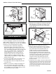
5. Attach the fan assembly to the fan bracket provided
in the finish bag. Use the #10 sheet metal screws
provided with fan kit. Do not remove finger guard
screws. (Fig. 16)
6. Connect snapstat leads. Disconnect the snapstat
module from the leads inside the snapstat bracket.
(Fig. 17) Bend open the snapstat bracket. Use
needle nose pliers to remove the black plastic
grommet from the bracket. Discard the bracket.
Insert the grommet and wires into the large hole at
the bottom right corner of the inner shroud. Feed the
snapstat wire leads through the grommet into the
stove interior. Connect the two wires to the two
snapstat extension leads attached to the inner
shroud or, on some models, in between the inner
and outer shroud.
7. Position the fan assembly so the ducts slide between
the inner and outer shroud. The inner shroud should
engage with the two slots in the ends of the bracket
so that bracket and shroud are interlocked. (Fig. 18)
Secure the bracket with the four sheet metal screws
provided in the finish bag.
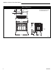
Rheostat
Retaining Collar
Rheostat Knob
ST347a
Fig. 14 Attach the fan rheostat.
Rheostat
A
A
Rear Shroud
Cover Plate
ST371
Fig. 13 Attach rear shroud cover plate to the rear shroud.
Install the Optional Fan
These instructions are for stoves with serial numbers
starting at #1457 (RNVODRN), #1944 (RNVODRP).
If you are installing the optional convection Fan Kit
#2767 (FK26), continue here. It is easiest to install fan
kit before connecting gas line. If you are not installing a
Fan Kit, proceed to Venting System Assembly.
1. The fan kit includes a Blower Assembly and a
Rheostat Assembly, connected by a cable. The
Blower Assembly mounts to the bottom rear of the
stove, and the Rheostat mounts to the left side of the
valve. The assembly includes a 'snapstat' which
automatically turns the fan On (or Off) above (or
below) approximately 109˚. The Rheostat also
provides a range of fan speed settings from Off
(which overrides the snapstat function) to High.
Unpack and inspect the Blower assembly. Confirm
that the fan spins freely.
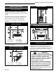
2. Loosen the four phillips head screws which secure
the rear shroud to the stove sides. (Fig. 15)
3. Carefully pull the shroud assembly away from the
rear of the stove.
4. With the rear shroud assembly in the upright posi-
tion, set the bottom of the shroud on a padded
surface to prevent scratching the surface. Unfasten
the four phillips head screws which attach the outer
shroud to the inner duct assembly.
ST713
Fig. 15 Remove rear shroud.
Rear
Shroud
Assembly
Snapstat
Wire
Rheostat
Wire
Fan
Bracket
Finger Guard
ST669
Fig. 16 Attach the fan assembly to the fan bracket.