
- Vermont Gas Heater Operating Manual


9
Radiance Natural Vent Gas Heater
20004409
A
ST363
Rear shroud
Cover Plate
(Shipping
Position)
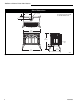
Fig. 11 Remove/replace rear shroud.
Rear
Shroud
1. The fan kit includes a Blower Assembly and a
Rheostat Assembly, connected by a cable. (Fig. 10)
The Blower Assembly mounts to the bottom rear of
the stove, and the Rheostat mounts to the left side of
the valve. The assembly includes a 'snapstat' which
automatically turns the fan On (or Off) above (or
below) approximately 109˚F. The Rheostat also
provides a range of fan speed settings from Off
(which overrides the snapstat function) to High.
Unpack and inspect the Blower assembly. Confirm
that the fan spins freely.
Not Used
On
Radiance
Snapstat
Assembly
Rheostat
Assembly
ST146
Fig. 10 Fan kit components.
2. Remove the rear shroud. (Fig. 11) Use work gloves
to protect your hands. Remove the rear shroud cover
plate. Remove the six sheet metal screws (‘A’, Fig. 9)
surrounding the draft hood opening. Remove the
shroud and set it aside.
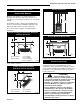
3. Position the fan behind the rear shroud. (Fig. 12)
Pass the fan rheostat assembly and snapstat
assembly beneath the stove toward the front.
4. The rheostat control switch attaches to the left side of
the valve bracket at the front of the stove. (Fig. 14)
• Remove the plug from the rheostat bracket.
• Insert the switch box shaft through the hole in the
back of the right side of the valve bracket, aligning the
locator pin with the smaller hole in that bracket.
• Attach the control knob to the rheostat shaft.
• Use the wire tie to secure the fan and rheostat wire
harnesses together.
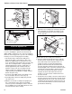
5. Attach the snapstat housing to the snapstat bracket
with two sheet metal screws and one #8 star washer.
(Fig. 12)
6. Attach the snapstat bracket, with the snapstat assem-
bly attached to it, to the horizontal surface on the
inside of the rear shroud. Use a sheet metal screw.
There are predrilled holes at each corner of the panel
for this. The vertical part of the snapstat bracket should
be 3/16” back from Edge ‘A’. (Fig. 12)
7. Attach the fan assembly to the rear shroud using two
1/4”-20 x 1/2” hex head bolts, two 1/4” -20 nuts and
one 1/4” star washer. (Fig. 12)
8. Reattach the stove’s rear shroud.
9. Reattach the rear shroud cover plate by fastening it to
the rear shroud as shown in Figure 13. The top edge
of the cover plate goes inside the rear shroud. Rein-
stall and tighten the six sheet metal screws around the
draft hood opening; see ‘A’, Figure 13. Use two screws
from the fan kit to fasten the rear shroud to the fan
shield; refer to ‘A’, Figure 13.
Plug the fan cord into a standard grounded 110 volt
household outlet.
Snapstat
Bracket
Hex Nuts
Edge ‘A’
Fan Shield
Slot
Star
Washer
1/4”-
20x1/2”
Hex Bolts
ST369
Fig. 12 Position fan behind rear shroud.
Snapstat
Housing