INSTALLER / CONSUMER SAFETY INFORMATION PLEASE READ THIS MANUAL BEFORE INSTALLING AND USING APPLIANCE. WARNING! IF THE INFORMATION IN THIS MANUAL IS NOT FOLLOWED EXACTLY, A FIRE OR EXPLOSION MAY RESULT CAUSING PROPERTY DAMAGE, PERSONAL INJURY OR LOSS OF LIFE. FOR YOUR SAFETY Installation and service must be performed by a qualified installer, service agency or the gas suppler.
Radiance Direct Vent/Natural Vent Gas Heater Table Of Contents PLEASE READ THE INSTALLATION & OPERATING INSTRUCTIONS BEFORE USING APPLIANCE. Thank you and congratulations on your purchase of a Vermont Castings stove. IMPORTANT: Read all instructions and warnings carefully before starting installation. Failure to follow these instructions may result in a possible fire hazard and will void the warranty.
Radiance Direct Vent /Natural Vent Gas Heater Installation & Operating Instructions The Radiance Direct Vent/Natural Vent Room Heater, Model Nos. 3350 thru 3354, 3360 thru 3369 and 3390 thru 3399, is a vented gas appliance listed to the ANSI standard Z21.88b-2002 and CSA-2.33b-2002 for Vented Room Heaters, and CSA 2.17M91, Gas-Fired Appliances For Use at High Altitudes.
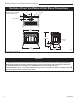
Radiance Direct Vent/Natural Vent Gas Heater Radiance Direct Vent/Natural Vent Stove Dimensions See Page 6 for Flue Collar Centerline Dimensions. ����������� � � 14���" (3.7cm) 7" Outer Dia. (1.8cm) 4���" (1.2cm) 29���" (7.6cm) �������� 28" (711mm) Supply Inlet 5" (127mm) 31" (7.9cm) 9���" (241mm) 18���" (464mm) 4188 Fig. 1 Radiance dimensions. ST126 RDV40 dimensions 10/99 Attention The Radiance stove is shipped from the factory as a Direct Vent Gas Heater.
Radiance Direct Vent /Natural Vent Gas Heater Installation Requirements The installation must conform with local codes or, in the absence of local codes, with the National Fuel Gas Code, ANSI Z223.1/NFPA 54 - latest edition. (EXCEPTION: Do not derate this appliance for altitude. Maintain the manifold pressure at 3.5” w.c. for Natural Gas, and 10” w.c. for Propane). In Canada, installation must be in accordance with the current CSA B-149.1 Installation Codes and/or local codes.
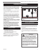
Radiance Direct Vent/Natural Vent Gas Heater Parallel Installation: Minimum Clearance and Flue Centerline, Direct Vent and Natural Vent Wall Centerline from Floor Direct Vent Only 42" (1070mm) Min. Alcove Width 4" (102mm) 48" (1220mm) Max. Alcove Depth ST130 A 6" (150mm) 6" (150mm) Fig. 3 Parallel installation, minimum back and side clearances, and flue centerlines.
Radiance Direct Vent /Natural Vent Gas Heater Horizontal Termination Direct Vent ONLY Gas Specifications Model Fuel Gas Control Max. Input BTU/h RDVODRN RDVODRP RDVODRFN RDVODRFP Nat Prop Nat Prop Millivolt Millivolt Comfort Control Comfort Control 35,000 35,000 35,000 35,000 Min. Input BTU/h 25,000 27,500 25,000 27,500 Weight: Fully assembled; 350 lbs. Gas Inlet and Manifold Pressures Inlet Minimum Natural 5.5” w.c. LP (Propane) 11.0” w.c. Inlet Maximum 14.0” w.c. 14.0” w.c.
Radiance Direct Vent/Natural Vent Gas Heater Vertical Termination - Direct Vent ONLY Vent Termination Clearances A vertical vent system must terminate no less than 8’ (2.44m) and no more than 40’ (12m) above the appliance flue collar. A 2¹⁄₄" restrictor plate (supplied) must be used, where specified, in all vertically terminated vent systems. (Refer to Figure 8) NOTE: The restrictor plate supplied with the vertical termination should be discarded.
Radiance Direct Vent /Natural Vent Gas Heater Vent Termination Clearances Your stove is approved to be vented either through the side wall, or vertical through the roof. • CFM Corporation does not require any opening for inspection of vent pipe. • Only CFM Corporation and Simpson DuraVent venting components specifically approved and labelled for this stove may be used. • Minimum clearances between vent pipes and combustible materials is one (1”) inch (25 mm), except where stated otherwise.
Radiance Direct Vent/Natural Vent Gas Heater General Venting Information - Termination Location INSIDE CORNER DETAIL G V H A N N D L V E C B V F B ����� ������ B V Ope Operable rable V B B B V J X X AIR SUPPLY INLET M I A CFM145a V VENT TERMINATION V Fixed Closed C = Clearance to permanently closed window D = Vertical clearance to ventilated soffit located above the terminal within a horizontal distance of 2’ (610mm) from the center line of the terminal E = Clearance to unvent
Radiance Direct Vent /Natural Vent Gas Heater Termination Clearances Termination clearances for buildings with combustible and noncombustible exteriors. Inside Corner Alcove Applications* Outside Corner G= Combustible 6" (152 mm) G F= Combustible 6" (152 mm) Noncombustible 2" (51 mm) V Noncombustible 2" (51 mm) V C V E O F Balcony with perpendicular side wall Balcony with no side wall D C E = Min. 6” (152 mm) for non-vinyl sidewalls Min. 12” (305 mm) for vinyl sidewalls O = 8’ (2.4 m) Min.
Radiance Direct Vent/Natural Vent Gas Heater Venting Requirements and Options Direct Vent ONLY Approved Vent System Components The Stardance Heater must be vented to the outdoors through an adjacent exterior wall or through the roof. The venting system must be comprised of the appropriate listed venting components specified on this page. These parts are available from DuraVent Corporation or your Vermont Castings Dealer. See Figure 4 for dimensions relevant to the standard minimum-vent kits.
Radiance Direct Vent /Natural Vent Gas Heater Assembly Procedures WARNING Failure to position the parts in accordance with these diagrams or failure to use only parts specifically approved for use with this heater may result in property damage or personal injury. This heater and components are heavy. Have help available for assembly. Tools Required • Phillips screwdriver (stub) • power drill • utility knife • reciprocating saw • metal drill bit: size 28 (.140”/3.
Radiance Direct Vent/Natural Vent Gas Heater WARNING This appliance is equipped with a three-prong (grounded) plug for your protection against shock hazard and should be plugged directly into a properly grounded three-prong receptacle. Do not cut or remove the grounding prong from this plug. Install the Optional Fan If you are installing the optional convection Fan Kit #2767 (FK26), continue here. It is easiest to install fan kit before connecting gas line.
Radiance Direct Vent /Natural Vent Gas Heater Venting System Assembly - Direct Vent General Information The Radiance is approved for installation only with the vent components listed on Page 11. Follow the vent component instructions exactly. 4. Attach the Inner Vent Assembly to the stove. • Run a bead of sealant around the bottom end of the starter pipe and attach the assembly to the stove using three 1/4-20 x 3/8” Phillips screws provided in the parts bag. (Fig. 20) For U.S.
Radiance Direct Vent/Natural Vent Gas Heater ST650 Fig. 21 Fasten outer pipe with #12 x 1/2” sheet metal screw. ST651 Fig. 23 Simpson Dura-Vent - install outer adapter pipe. Side Wall Termination Assembly Install the Vent Adapter Pipe (Simpson Dura-Vent Components) 1. Install the Restrictor Plate. Consult Page 7 to determine whether the restrictor plate is needed. If so, ST650 place the restrictor the inner flue collar install plate outerwithin adpater as shown in Figure 18. 4/20/01 djt 2.
Radiance Direct Vent /Natural Vent Gas Heater 12” (305mm) Max. Length Sleeve #8 Sheet Metal Screws Firestop ZCS103 Fig. 25 Assemble the wall sleeve and firestop. ZCS103 For DuraVent pipe only: Install vent pipe by alignZero Clearance Sleeve ing the locking system together, sliding the pipes & Firestop together and12/6/99 twisting djt clockwise. 6. Install the elbow using 3 sheet metal screws at each joint. 7.
Radiance Direct Vent/Natural Vent Gas Heater 11. For CFM only: Install Charcoal Gray Pipe Rings (#7FSDRG) or Polished Brass Pipe Rings (#7FSDRP) at pipe joints, if desired. Recessed Wall Firestop Seal Both Terminal Ends Finishing Collar Sheet Metal Screws and Bracket Wall Screws and Anchors Waterproof Seal Around Pipe 7” Pipe Wall Plate Caulk Plate Joint with Weatherproof Sealant ST217 Fig. 29 Install the vent terminal.
Radiance Direct Vent /Natural Vent Gas Heater Make certain the vent system conforms to all other requirements for vertical termination as specified on Page 9. This installation will require you to first determine the roof pitch and use the appropriate vent components. Refer to Figure 9 on page 9. 1. Locate the final position of the stove, observing all clearances for both the vent and the stove. 2. Plumb to the center of the inner (4”) flue collar from the ceiling above, and mark that location. 3.
Radiance Direct Vent/Natural Vent Gas Heater The Radiance stove, when installed as a Natural vent heater, includes a vent safety switch. (Page 34, Figure 67) Operating the stove when it is not connected to a properly installed and maintained venting system, or tampering with or disconnecting the vent safety switch, can result in carbon monoxide (CO) poisoning and possible death. Install Log Set Before beginning log installation, remove stove front and glass frame. Refer to Figures 36 and 37. For U.S.
Radiance Direct Vent /Natural Vent Gas Heater Rear Log Bracket Log rests on decorative grate LG158 LG155 Fig. 40 Completed log installation. Fig. 38 Radiance firebox. LG156 Radiance logs Right Log djt Right 4/23/01 Rear Log Lava Rock Left Rear Log Left Rear Log LG155 Top View Radiance logs installed 4/24/01 djt Right Rear Log Lava rock may be placed in this area Decorative Grate LG160 Fig. 41 Lava rock placement.
Radiance Direct Vent/Natural Vent Gas Heater CAUTION This appliance should only be connected by a qualified gas technician. Test to confirm manifold pressures as specified below. The Radiance Heater and its individual shutoff valve must be disconnected from the gas supply piping during any pressure testing of that system at test pressures in excess of 1/2 psig (3.5 kPa).
Radiance Direct Vent /Natural Vent Gas Heater Operation The Radiance is shipped with the operable door front plate. The stove may be operated with the doors either open or closed. To open the front doors, insert the handle into the door latch stub and turn it to the right and up. (Fig. 44) When not in use, the handle may be stored in the handle holder on the right side of the rear shroud. (Fig. 45) Pilot Assembly Counterclockwise to Open ST476 Fig. 46 Pilot Assembly location.
Radiance Direct Vent/Natural Vent Gas Heater Lighting and Operating Instructions FOR YOUR SAFETY READ BEFORE LIGHTING WARNING:If you do not follow these instructions exactly, a fire or explosion may result causing property damage, personal injury or loss of life. A. This heater has a pilot which must be lit manually. When lighting the pilot follow these instructions exactly. B. BEFORE LIGHTING smell all around the heater area for gas.
Radiance Direct Vent /Natural Vent Gas Heater Troubleshooting / Honeywell #8420 Gas Control System NOTE: Before troubleshooting the gas control system, be sure the external gas shutoff is in the “ON” position. WARNING: REMOVE THE GLASS PANEL BEFORE PERFORMING ANY GAS CONTROL SERVICE WORK. SYMPTOM 1. Spark ignitor will not light 2. Pilot will not stay lit after carefully following the lighting instructions 3.
Radiance Direct Vent/Natural Vent Gas Heater Instructions for RF Comfort Control Valve The Comfort Control valve allows remote control of temperature, fan and flame appearance. NOTE: The antenna should hang in free air away from grounded metal. Operation 1. If the manual switch is in remote position, switch it to LOCAL. (Fig. 49) 2. Turn the pilotstat knob counterclockwise from OFF to the PILOT position, push the knob down, and hold in position.
Radiance Direct Vent /Natural Vent Gas Heater Auto Mode Pilot Assembly In the AUTO mode, the room temperature, set temperature, flame and fan levels will be shown. AUTO will appear next to both the flame and fan icons. Blower When the control is in the AUTO mode, the main burner will turn on/off or modulate based on the heat needed to maintain the set temperature. The flame level will change automatically to optimize the heat output needed to maintain the set temperature.
Radiance Direct Vent/Natural Vent Gas Heater Comfort Valve System Control Sequence Of Operation With Transmitter Set manual switch to local or remote Five minute wait period Light pilot burner Did the LED stop blinking? No Review LED failure analysis. Release pilotstat knob. Yes Turn pilotstat knob from PILOT to ON. Cycle switch once and leave in remote. Press any key on transmitter for recognition operation.
Radiance Direct Vent /Natural Vent Gas Heater Auto Path If the manual switch is set to REMOTE, press the mode button to display AUTO on the transmitter. Does the transmitter display the room and temperture setting? Move switch from LOCAL to REMOTE. Press any key within 30 seconds.
Radiance Direct Vent/Natural Vent Gas Heater Fuel Conversion Instructions WARNING! This conversion kit shall be installed by a qualified service agency in accordance with the manufacturer’s instructions and all applicable codes and requirements of the authority having jurisdiction. If the information in these instructions is not followed exactly, a fire, explosion or production of carbon monoxide may result causing property damage, personal injury or loss of life.
Radiance Direct Vent /Natural Vent Gas Heater E Cap Lift Open HI LO LO OF CO100 O Center Screw IL FP Hi-Lo Knob OT HI Fig. 55 Remove center screw CO100 from Hi-Lo knob. D Gas conversion knob 3. Insert blue painted screwHI-LO when 3/15/99 djt converting to natural gas and red painted screw when converting to LP. 4. Tighten screw (do not over tighten), replace cap. SIT 820 Valve 1.
Radiance Direct Vent/Natural Vent Gas Heater Motor Top Cap Center Plunger Pilot Hood OT PIL OFF • Red - LP CO105 Fig. 60 Remove pilot hood. (Your pilot may have a different appearance.) CO105 Gas ConversionPilot Orifice Pilot 2/15/99 djt CO106b Fig. 61 Remove pilot orifice. NOTE: Be sure burner leg remains at a 90° angle to firebox base after conversion. Models 3352, 3354, 3390 thru 3399 (RF Models) Only CO106a 1. Follow procedure for pilot type 2 to replace pilot orifice. Gas Conversion 2.
Radiance Direct Vent /Natural Vent Gas Heater Table 1. Injector Orifice Size Matrix Kit # 000-5002 Conversion to Natural Gas Part # Rear Part # Front #51 / .067” 30000449 #40 / .098” 20004263 Input (BTU/h) Minimum Maximum 25,000 35,000 000-5009 Kit # 000-5003 Conversion to LP Part # Rear Front #57 / .043” 20004587 #54 / .055” Part # 20000130 Input (BTU/h) Minimum Maximum 27,500 35,000 000-5010 Table 2.
Radiance Direct Vent/Natural Vent Gas Heater Maintenance Your Radiance Gas Heater will provide years of service with minimal upkeep. The following procedures will help ensure that your stove continues to function properly. Annual System Inspection Have the entire heater and venting system inspected annually by a qualified gas technician. Replace any worn or broken parts. Logset and Burner / Cleaning and Inspection Cleanliness is critical to the proper function of the heater.
Radiance Direct Vent /Natural Vent Gas Heater ST179 Fig. 66 Wrap the gasket material around the outside edge of the glass. ST141 Fig. 65 Release the latches to remove the glass frame. Gasket Replacement ST141 The Radiance Gas Heater uses a ‘tadpole’ type gasket pull glass latch 10/99 and the frame. In time, to seal between the glass panel this gasket can become brittle and compressed and should be replaced. New gasket is available from your dealer. Shut off the gas supply and allow the stove to cool.
Radiance Direct Vent/Natural Vent Gas Heater Wiring Diagrams OFF ON Thermopile Black On/Off Switch Wiring TP/TH BL Millivolt Gas Valve TP Black TH FAN POWER CORD Chassis Ground BL Thermopile Black St124b on/off/switch wiring 1/11/00 djt Strain Relief ON / OFF Rheostat Millivolt Gas Valve Black Snapstat ST124c WHT LK Fig. 68 On/off switch and optional thermostat circuit.
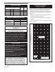
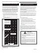
Radiance Direct Vent /Natural Vent Gas Heater 2 1a 7 6 NT ME CE 8 7 3 4 5 1b 1c 10a,b 24 T OFF O H L PILOT ADJ OFF • 23 D ON • 16 REMOTE 15 T PILO LOCAL 12a 13 14 25 ON O LE I PIL 41 9 38 11a,b 19 12b 17 39 26 12c 22 27 18 44 45 28 49 20a,b 34 21a,b 32 33 29a,b, c,d 46 47 31 30 36 53 35 52 48 51 55a,b 37 50 56 CFM Corporation reserves the right to make changes in design, materials, 4188 specifications, prices and discontinue colors and product
Radiance Direct Vent/Natural Vent Gas Heater Radiance Direct Vent/Natural Vent Gas Heater (RDVOD) Models: 3225 thru 3232, 3350 thru 3354, 3360 thru 3369, 3390 thru 3399 (continued) Ref. Description 7. 8. 9. 10a. 10b. 11a. 11b. 12a. 13. Gasket, Glass Med.
Radiance Direct Vent /Natural Vent Gas Heater Radiance Direct Vent/Natural Vent Gas Heater (RDVOD) Models: 3225 thru 3232, 3350 thru 3354, 3360 thru 3369, 3390 thru 3399 (continued) Ref. Description 47. 48. 49. 50. 51. 52. 53. 54. 55a. 55b. 56. 57. Right End Leg Control Door Handle Assembly Gasket, HE Door Top FK26 Fan Subassembly (RF Only) Grille, RDV40 Screen, Top RDV40 Valve Nova SIT820.662 RN (Serial #’s starting with 4940) Valve Nova SIT820.
Radiance Direct Vent/Natural Vent Gas Heater Optional Accessories Fan Kits FK26 Fan The FK26 fan helps distribute heated air from within the firebox out into the room. The fan is controlled by a snapstat that turns power on and off as the firebox temperature rises above and falls below a preset temperature. A rheostat provides for variable fan speeds. Specifications Screen Kit An optional screen, R40SK, for use with the operable doors is available to allow the doors to be left in the open position.
Radiance Direct Vent /Natural Vent Gas Heater 20004188 41
Radiance Direct Vent/Natural Vent Gas Heater 4242 20004188
Radiance Direct Vent /Natural Vent Gas Heater LIMITED LIFETIME WARRANTY PRODUCT COVERED BY THIS WARRANTY All Vermont Castings gas stoves, gas inserts, and gas fireplaces, and all Majestic brand gas fireplaces equipped with an Insta-Flame Ceramic Burner, or standard steel tube burner.
Efficiency Ratings Model RDVODRN RDVODRP RDVODRFN RDVODRPN EnerGuide Ratings Fireplace Efficiency (%) 60.7 60.7 60.7 60.7 CFM Corporation 410 Admiral Blvd. • Mississauga, Ontario, Canada L5T 2N6 800-668-5323 • www.cfmcorp.