Multisided Top/Rear Vent Convertible Direct Vent Fireplaces: 360DVS2 360DVS3 360DVSL 360DVSR INSTALLER/CONSUMER SAFETY INFORMATION PLEASE READ THIS MANUAL BEFORE INSTALLING AND USING APPLIANCE IMPORTANT: Read all instructions and warnings carefully before starting installation. Failure to follow these instructions may result in a possible fire hazard, and will void the warranty.
360DVS Series Direct Vent Fireplaces Installation & Operating Instructions This gas appliance should be installed by a qualified installer in accordance with local building codes and current CSA-B149.1 Installation Codes for Gas Burning Appliances and Equipment. If the unit is being installed in a mobile home, the installation should comply with the current CAN/CSA Z 240.4 code. For U.S.A. Installations, follow local codes and/or the current National Fuel Gas Code, ANSI Z223.1/NFPA 54.
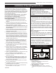
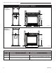
60 DVS Series Direct Vent Fireplaces Fireplace Dimensions - 360DVS2 I Rear Vent Configuration J J K H H K B G E A E A D Electrical Access Electrical Access J J K Gas Line Access J Gas Line Access F C J Top Vent Configuration 6326 360DVS2 rear vent specs H J K J K H K B G C I E A E A D Electrical Access Electrical Access J K J F Fig. 2a Fireplace specifications—360DVS2 Ref.
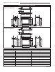
360DVS Series Direct Vent Fireplaces Fireplace Dimensions - 360DVS3 / 306DVSL / 360DVSR K Rear Vent Configuration I J H H B K ROD A E G D Electrical Access J Gas Line Access J K C K Top Vent Configuration H I J C F B 6326 360DVS3 rear vent specs H K B G A E Electrical Access J K D Gas Line Access J B F C 6326 Fig. 2b Fireplace specifications—360DVS3/ 360DDVSL/ 360DVSR 360DVS3 top vent Ref.
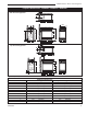
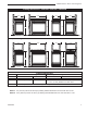
360 DVS Series Direct Vent Fireplaces Framing Dimensions - 360DVS2 Rear Vent Configuration ROD ROH CFM121 ROW Top Vent Configuration ROD CFM121 360DVS2 REAR VENT CONFIGURATION 8/10/00 ROH ROW CFM122 Fig. 3a Fireplace framing dimensions—360DVS2 Ref. ROD ROH ROW 6 CFM122 360DVS2 - TOP VENT CONFIGURATION Framing Dimensions 8/10/00 Rear Vent Configuration Top Vent Configuration 24” (610 mm) minus two times finishing material thickness to be even with face of unit.
360DVS Series Direct Vent Fireplaces Framing Dimensions - 360DVS3 / 360DVSL / 360DVSR Rear Vent Confiration ROD ROW ROH ROH 360DVSL ROD CFM123_360DVS3_dims_RV2 REAR VENT CONFIGURATION 8/10/00 rev. 8-23-02 rjs ROW 360DVSR ROD 360DVS/3/L/R CFM123 ROD ROH ROH ROH 360DVSL ROH 360DVS3 360DVS/3/L/R Top Vent Configuration ROD ROD 360DVS3 360DVSR CFM124 Fig. 3b Fireplace framing dimensions—360DVS3/ 360DVSL/ 360DVSR CFM124_360DVS3_TV2 TOP VENT CONFIGURATION Ref.
360 DVS Series Direct Vent Fireplaces Clearance to Combustibles Appliance Top .........................................0” (0 mm) to standoff Bottom ..................................................... 0” (0 mm) Vent End ....................... 1/2” (13 mm) to rear panel Nonvent End (DVS2) .............................. 0” (0 mm) Venting Concentric sections of DV Vent: Top, bottom & sides .............................. 1” (25 mm) Nonconcentric sections of DV Vent: Side and bottom ...........................
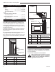
360DVS Series Direct Vent Fireplaces Gas Inlet & Manifold Pressures Framing & Finishing 1. Choose the unit location. 2. Place the unit into position and secure it to the floor with 1¹⁄₂” (38mm) screws or nails. Holes to secure the unit to the floor are located behind the access door grille on the left and right sides of the unit. 3. Frame in the fireplace with a header across the top. It is important to allow for the finished wall face when setting the depth of the frame. 4.
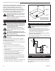
360 DVS Series Direct Vent Fireplaces The gas control is equipped with a captured-screw type pressure test point, therefore it is not necessary to provide a 1/8” test point upstream of the control. When using copper or flex connector, use only approved fittings. Always provide a union when using black iron pipe so that the gas line can be easily disconnected for burner or fan servicing. Refer to the gas specification for pressure details and ratings.
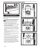
360DVS Series Direct Vent Fireplaces Remove These Screws Remove These Screws FP1430 Fig. 8 Alternate switch location. Optional Top Vent Application This appliance is shipped as a rear vent unit. If the installation layout requires the unit to be a top vent configuration, the appliance can be converted by following the steps below. Outer Collar Adapter FP1431 Fig. 9 Remove screws from outer collar adapter.
360 DVS Series Direct Vent Fireplaces Electronic Gas Control Valve This appliance may be fitted with a Honeywell ignition module. Installation of the remote ON/OFF starter switch on electronic ignition units (Fig. 12): 1. Thread the wiring through the holes on the side panels of the appliance. Take care not to cut the wire or insulation on metal edges. Route the wire to a conveniently located receptacle box. 2. Attach the wire to the ON/OFF switch and install the switch into the receptacle box. 3.
360DVS Series Direct Vent Fireplaces General Venting Information - Termination Location INSIDE CORNER DETAIL V D H A V N N E L V B V F C B Fixed Closed B V Ope rab Operable le V B CFM145a G V VENT TERMINATION B V Fixed Closed V J G X B I A X AIR SUPPLY INLET M V K X G A V V AREA WHERE TERMINAL IS NOT PERMITTED Canadian Installations1 CFM145a (30cm) DV Termin Location 5/01/01 Rev.
360 DVS Series Direct Vent Fireplaces Termination Clearances Termination clearances for buildings with combustible and noncombustible exteriors. Inside Corner Recessed Location Outside Corner A= Combustible 6"(152mm) Noncombustible 2"(50mm) A V B= Combustible 6"(152mm) Noncombustible 2"(50mm) V C D E C V B Balcony with perpendicular side wall Balcony with no side wall V V G= Combustible & Noncombustible 12"(305mm) C = Maximum depth of 48" (1219mm) for recessed location.
360DVS Series Direct Vent Fireplaces How to Use the Vent Graph Rear Wall Application The vent chart should be read in conjunction with the following vent installation instructions to determine the relationship of the vertical and horizontal dimensions of the vent system. When installed as a rear vent unit this appliance may be vented directly to a termination located on the rear wall behind the appliance. 1. Determine the height of the center of the horizontal vent pipe exiting through the outer wall.
360 DVS Series Direct Vent Fireplaces STEP 5 Vent Opening for Combustible Wall Guide vent through the vent hole as you place the appliance in its installed position. Guide the 4” (102 mm) and 7” (178 mm) collars of the vent termination into the outer ends of the venting. 9³⁄₈” (240mm) Do not force the termination. If the vent pipes do not align with the termination, remove and realign the venting at the appliance flue collars.
360DVS Series Direct Vent Fireplaces Horizontal plane means no vertical rise exists on this portion of the vent assembly. • The maximum number of 90˚ elbows per side wall installation is three (3). • If a 90˚ elbow is fitted directly on top of the fireplace flange, the maximum horizontal vent run before the termination or a vertical rise is 36” (914mm). Max. 20” (508mm) Max. 36” (914mm) • The maximum number of 45° elbows permitted per side wall installation is two (2).
360 DVS Series Direct Vent Fireplaces STEP 4 Vent Opening for Combustible Wall Apply a bead of silicone to the inner and outer flue collars of the fireplace and using appropriate length of pipe section(s) attach to fireplace with three (3) screws. Follow with the installation of the inner and outer elbow, again secure joints as described in “Connecting Vent Pipes” section.
360DVS Series Direct Vent Fireplaces 2” (51 mm). Secure termination to the wall with screws provided, and caulk around the wall plate to weatherproof. Zero Clearance Sleeve (if required) One alternative to screwing the termination directly to the wallis the use of expanding plugs or an approved exterior construction adhesive.
360 DVS Series Direct Vent Fireplaces Vertical Through-the-Roof Application This Gas Fireplace has been approved for: 1 + 2 + 3 + 4 = 270° • Vertical installations up to 40’ (12 m) in height. Up to a 10’ (3 m) horizontal vent run can be installed within the vent system using a maximum of two 90° elbows. (Fig. 30) 1 2 3 4 Max. Height 40’ (12.2m) Min. Height 8’ (2.4m) 1 2 3 4 Max. 10’ (3m) FP1444 Fig. 31 Maximum elbow usage. Support Straps Every 36” (914mm) Min. 2' (610 mm) Max. 10’ (3m) Max.
360DVS Series Direct Vent Fireplaces Vertical Through-the-Roof Installation 1. Locate your fireplace. 2. Plumb to center of the (4”) flue collar from ceiling above and mark position. 3. Cut an opening equal to 9³⁄₈” x 9³⁄₈” (240 x 240mm). 4. Proceed to plumb for additional openings through the roof. In all cases, the opening must provide a minimum of 1” (25 mm) clearance to the vent pipe, i.e., the hole must be at least 9³⁄₈” x 9³⁄₈” (240 x 240mm). 5. Place fireplace into position. 6.
360 DVS Series Direct Vent Fireplaces Twist Lock Venting Components 7TDVRVT Through-the-Wall Rear Vent Termination 584A venting components rear vent term 4/6/99 djt Starter Kit Model 7TDVSK - Sidewall Starter Kit Model 7TDVSKV - Vertical Venting for 7TDVSKV-A: order 1/12 to 6/12 roof pitch for 7TDVSKV-B: order 7/12 to 12/12 roof pitch for 7TDVSKV-F: order flat roof Starter Kit Model 7TDVSKS - Snorkel Kit Snorkel Termination - 7TDVSNORK for Below Grade Installation 45˚ Elbow 7TDVT45 for Rear Vent to Vertica
360DVS Series Direct Vent Fireplaces Operating Instructions Glass Information Only glass approved by CFM Corporation should be used on this fireplace. • The use of any non-approved replacement glass will void all product warranties. • Care must be taken to avoid breakage of the glass. • Do not operate appliance with glass front removed, cracked or broken.
360 DVS Series Direct Vent Fireplaces Glass Cleaning It is necessary to periodically clean glass. During startup, condensation, which is normal, forms on the inside of the glass. This condensation causes lint, dust and other airborne particles to cling to glass surface. Also initial paint curing may deposit a slight film on the glass. It is therefore recommended glass be cleaned two or three times with a non-ammonia based household cleaner and warm water.
360DVS Series Direct Vent Fireplaces Side of Fireplace B120 B125 B122 B126 Venting Side B123 B124 B121 LG320 Fig. 40 360DVS log placement. Venting Side B121 Side of Fireplace B123 B120 LG320 360DVS logs B122 B126 B125 LG321 Fig. 41 360DVS log placement. Your log set contains Ember Material and two types of Lava Rocks. Set these materials in place after the logs have been installed. Ember Material (Pt.
360 DVS Series Direct Vent Fireplaces HI Turn counterclockwise to increase flame height LO Turn clockwise to decrease flame height 3/8” - 1/2” (10 - 13mm) Fig. 43 Flame adjustment knob for SIT valve. Flame Characteristics FP390 F584-703 Fig. 45 Correct pilot flame appearance. It is important to periodically performKNOB a visual check FLAME ADJUSTMENT 11/21/96 of the pilot and burner flames. Compare them to the pictorials illustrated below. (Figs.
360 DVS Series Direct Vent Fireplaces Maintenance Burner and Burner Compartment It is important to keep the burner and the burner compartment clean. At least once per year remove the logs and lava rock/ember material. Vacuum and wipe out the burner compartment. Remove and refit the logs per the instructions in this manual. Always handle the logs with care as they are fragile and may also be hot if the fireplace has been in use. FK24/FK12 Fan Assembly The fan unit requires periodic cleaning.
360DVS Series Direct Vent Fireplaces 1 1g 1f 1c 1a 8 1b 1e 1d 3a/b 2 11 9 14 O H 7 4a/b OFF 12 PILOT ADJ L ON P IL O I 10 6 16a/b T 13 5a/b 11 15a/b 20 22 24 25 26 29 27 19 28 23 18 21 17 31a/b 36 30 35 34a/b 37 25 LO 32 HI 33 CFM Corporation reserves the right to make changes in design, materials, specifications, prices and discontinue colors and products at any time, 6326 without notice.
360 DVS Series Direct Vent Fireplaces 360DVS Series Ref. 1. 1a. 1b. 1c. 1d. 1e. 1f. 1g. 2. 3a. 3b. * * * 4a. 4b. 5a. 5b. 6. 7. 8. * * * * * * * 9. 10. 11. 12. 13. 14. 15a. 15b. 16a. 16b. 17. 18. * * * * 19. * * 20.
360DVS Series Direct Vent Fireplaces 360DVS Series (continued) Ref. 21. 22. 23. 24. 25. 26. * * * * * 27. 28. 29. 30. * * * * * * * * * * * * 31a. 31b. 32. 33. 34a. 34b. 35. 36. 37.
360DVS Series Direct Vent Fireplaces LIMITED LIFETIME WARRANTY PRODUCT COVERED BY THIS WARRANTY All Vermont Castings gas stoves, gas inserts, and gas fireplaces, and all Majestic brand gas fireplaces equipped with an Insta-Flame Ceramic Burner, or standard steel tube burner.
Efficiency Ratings Model 360DVS2RN 360DVS2RP 360DVS2EN 360DVS2EP 360DVS3RN 360DVS3RP 360DVS3EN 360DVS3EP 360DVSLRN 306DVSLRP 360DVSLEN 360DVSLEP 360DVSRRN 360DVSRRP 360DVSREN 360DVSREP EnerGuide Ratings Fireplace Efficiency (%) 62.4 62.4 62.4 62.4 62.4 62.4 62.4 62.4 62.4 62.4 62.4 62.4 62.4 62.4 62.4 62.4 Steady State (%) Fan-OFF Fan-ON 83 84 83 84 83 84 83 84 83 84 83 84 83 84 83 84 83 84 83 84 83 84 83 84 83 84 83 84 83 84 83 84 CFM Corporation 2695 Meadowvale Blvd.