
- Vermont Castings Direct Vent Homeowner's Manual 33XDV, 36XDV, 39XDV


XDV Direct Vent Gas Fireplace
30
10009383
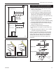
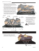
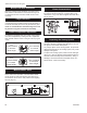
Large Lava Rock
The large bag of lava rock provided with this fireplace
must be placed on the firebox base around the sides of
the burner assembly and on the tray beneath the grate.
Under no circumstances should this large lava rock
be placed on any part of the burner assembly.
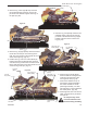
Burner Lava Rock Placement
Place the contents of the small bag of ceramic burner
lava embers on the burner in front of the front logs. Do
not place burner lava rock in the inside corners of the
front logs.
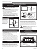
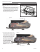
Fig. 66 Flame adjustment knob for SIT valve.
L
O
H
I
FP390
FLAME ADJUSTMENT KNOB
11/21/96
Turn
counterclockwise
to increase
flame height
Turn clockwise
to decrease
flame height
SIT 820 Valve
Fig. 65 Flame adjustment knob for Honeywell valve.
LO
HI
Turn
counterclockwise
to decrease
flame height
Turn clockwise
to increase
flame height
HV102
Honeywell hi/lo knob
4/5/99 djt
Honeywell Valve
Flame & Temperature Adjustment
For fireplaces equipped with Hi/Lo valves, flame adjust-
ment is accomplished by rotating the Hi/Lo adjustment
knob located near the centre of the gas control. (Fig. 65
or 66)
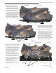
Manual ON/OFF Valve
The Manual ON/OFF valve was designed particularly
for the main burner operation. The main burner flame
can be turned on and off as desired. This valve is rec-
ommended to be set to the “ON” position when lighting
the unit. (Fig. 67)
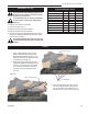
Flame Characteristics
It is important to periodically perform a visual check of
the pilot and the burner flames. Compare them to Fig-
ures 68-69. If any of the flames appear abnormal call a
service person.
3/8” - 1/2”
(10 - 13 mm)
Fig. 68 Correct pilot flame appearance.
F584-703
SIT Pilot
PSE Pilot
Inspecting the Venting System
This appliance venting system is designed and con-
structed to develop a positive flow adequate to remove
flue gases to the outside atmosphere.
Any foreign objects in the venting system, except those
designed specifically for the venting system, may cause
spillage of flue gases.
To inspect the venting system, make sure the main gas
valve is off. Remove window frame assembly (Refer to
Window Frame Assembly Removal Section). Using a
flashlight, check the area above the baffle in the com-
bustion dome. Clean if necessary.
FP1613
Fig. 67 Manual ON/OFF valve shown on RN/RP models.
F
l
a
m
e
A
d
j
u
s
t
m
e
n
t
F
a
n
S
p
e
e
d
Ignitor
ON
OFF
PILOT
ON
OFF
ON
OFF
FP1612
Copreci
manual on/off
valve
4/06