
- Vermont Castings Direct Vent Homeowner's Manual 33XDV, 36XDV, 39XDV

XDV Direct Vent Gas Fireplace
42
10009383
Fuel Conversion Instructions
Honeywell Comfort Control Valve ONLY
WARNING: The conversion must only be
undertaken by a qualified, certified gas ap-
pliance installer.
FP1037
Honeywell
comfort valve
3/22/00 djt
LOCAL
REMOTE
ON
•
PILOT
OFF
•
LED
Motor Top Cap
Piezo Ignitor
Local/
Remote Switch
Pilotstat
Knob
LED
Plug
Antenna
FP1037
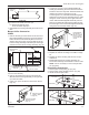
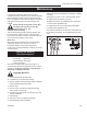
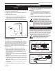
Fig. 83 Comfort control valve.
Installation Precautions
Before proceeding, turn control knob on valve to OFF
and turn gas supply OFF. Turn OFF any electricity that
may be going to the appliance. CAUTION: Logs may
be hot!
Conversion Procedure
1. Open bottom grille to gain access to valve. Remove
glass door. (Refer to “Window Frame Assembly Re-
moval Section” Page 24, Fig. 48)
2. Remove logs if previously installed. CAUTION: Logs
may be hot!
3. Remove and replace plug on lower right hand side of
the valve; Red for LP and blue for NG. (Fig. 83)
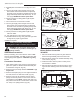
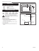
4. Remove motor top cap. Depress and turn center
plunger until arrow points to correct screw. Red for
LP and Blue for NG.
NOTE: Plunger will “snap” into
NG position when arrow is close to blue screw. It will
not “snap” at LP (Red) position. (Fig. 84)
4. Reinstall pilot hood and be sure to align with index
tab.
5. Turn the gas supply valve and gas valve on and
test for leaks. Use a 50/50 solution of liquid soap
and water to test for leaks at gas fittings and joints.
Apply water/soap solution with brush only - do not
over apply. NEVER test with an open flame.
6. Follow procedure on rating plate to light the pilot.
Check for leaks.
7. Turn main burner on and check for leaks.
8. Turn the gas supply valve and gas valve on and
test for leaks. Use a 50/50 solution of liquid soap
and water to test for leaks at gas fittings and joints.
Apply water/soap solution with brush only - do not
over apply. NEVER test with an open flame.
9. Follow procedure on rating plate to light the pilot.
Check for leaks.
10. Turn main burner on and check for leaks.
11. Reinstall bracket rear log, front grate and logs. Refer
to Page 25 for proper log placement.
Installation complete.
FP1037b
comfort valve
convert
3/6/01 djt
LOCAL
REMOTE
ON
•
PILOT
OFF
•
LED
Center
Plunger
Blue
- NG
Red - LP
Motor Top Cap
FP1037b
Fig. 84 Depressd and turn center plunger.
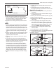
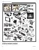
Burner Orifice Conversion
33/36XDV
1. Remove bracket rear log and front grate. Remove
burner housing assembly and front burner tube.
2. Remove burner orifice from manifold assembly using
7/16” wrench. (Fig. 85)
3. Install conversion orifice in place of orifice just re
-
moved. Refer to Table 2.
4. Remove both air shutters from burner pan by remov
-
ing air shutter retaining screw then air shutter. (Fig.
86)
Fig. 85 Remove burner assembly.
Rear Burner Orifice:
(Refer to Conversion Kit
Orifice Chart)
Front Burner Orifice:
(Refer to Conversion Kit
Orifice Chart)
Main Burner
Assembly
Pilot
Location
Front Burner
Tube
FP1612