
- Vermont Castings Pinnacle & Stardance Direct Vent, Rear Vent Gas Heater Homeowner's Installation SDVR, PDV20: 3920, 3926, 3930, 3936, 3960, 3966, 3970, 3976, 4065, 4070, 4075, 4080


26
Pinnacle & Stardance Direct Vent - Rear Vent Gas Heaters
20007066
Operation
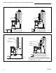
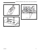
The Stardance is operated with the operable door front
plate in place with the doors open or closed. To open
the front doors, insert the handle into the door latch
stub and turn it to the left and up. (Fig. 45) When not in
use, the handle may be stored in the handle holder on
the right side of the rear shroud. (Fig. 46)
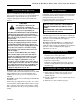
Your First Fire
Read these instructions carefully and familiarize
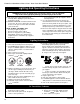
yourself with the burner controls shown in Figure 47.
Locate the pilot assembly, Figure 48. Follow the
lighting instructions on Page 28 exactly.
During the first fire, it is not unusual to smell some odor
associated with new logs, paint and metal being
heated. Odors should dissipate within a few hours. You
can open a window to provide fresh air to alleviate the
condition.
Pilot and Burner Inspection
Each time you light your heater check that the pilot
flame and burner flame pattern are as shown in Figures
50 through 52. If flame patterns are incorrect, turn the
heater off. Contact your dealer or a qualified gas
technician for assistance. Do not operate the heater
until the pilot flame is correct.
Follow regular maintenance procedures as described
on Page 36.
Clockwise to
Open
Counterclockwise
to Close
ST621
Fig. 45 To open the front doors, turn handle clockwise.
Handle
Holder
ST624
Fig. 46 When not in use, store handle in the handle holder.
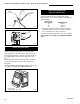
PILOT
ON
OFF
PILOT
ADJ
L
O
H
I
TPTH
TH
TP
Piezo Ignitor
Button
Pressure Tap
Regulator
Control Knob
Gas Control Knob
Pilot Adjustment
Screw
HV104
Fig. 47 RN & RP valve control.
Flame & Temperature Adjustment
For stoves equipped with HI/LO valves, flame
adjustment is accomplished by rotating the HI/LO
adjustment knob located near the center of the gas
control valve. (Fig. 49)
LO
HI
Turn
counterclockwise
to decrease
flame height
Turn clockwise
to increase
flame height
Fig. 49 Flame adjustment knob for Honeywell valve.
Flame Characteristics
It is important to periodically perform a visual check of
the pilot and the burner flames. Compare them to
Figures 50 through 52.
If any of the flames appear abnormal call a service
person.
Fig. 48 Pilot Assembly location.
Pilot
Assembly
ST476a