Builder Rear Vent Direct Vent Models: 33LDVR, 36LDVR, 39LDVR, 43LDVR INSTALLER/CONSUMER SAFETY INFORMATION PLEASE READ THIS MANUAL BEFORE INSTALLING AND USING APPLIANCE WARNING! IF THE INFORMATION IN THIS MANUAL IS NOT FOLLOWED EXACTLY, A FIRE OR EXPLOSION MAY RESULT CAUSING PROPERTY DAMAGE, PERSONAL INJURY OR LOSS OF LIFE. FOR YOUR SAFETY Installation and service must be performed by a qualified installer, service agency or the gas supplier. WHAT TO DO IF YOU SMELL GAS: • Do not try to light any appliance.
LDVR Series Direct Vent Gas Fireplace Table of Contents PLEASE READ THE INSTALLATION & OPERATING INSTRUCTIONS BEFORE USING APPLIANCE. Thank you and congratulations on your purchase of a CFM Corporation fireplace. IMPORTANT: Read all instructions and warnings carefully before starting installation. Failure to follow these instructions fully may result in a possible fire hazard and will void the warranty. Installation & Operating Instructions Important Curing/Burning Instructions ..............................
LDVR Series Direct Vent Gas Fireplace Installation & Operating Instructions This gas appliance should be installed by a qualified installer in accordance with local building codes and with current CSA-B149.1 Installation codes for Gas Burning Appliances and Equipment. For USA Installations follow local codes and/or the current National Fuel Gas Code. ANSI Z223.1/NFPA 54.
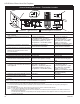
LDVR Series Direct Vent Gas Fireplace Fireplace Dimensions Rough Opening Depth S E R F U S V - Rough Opening Width Rough Opening Height T Low Voltage Access B Centerline of 7" Collar Q D C Gas Line Access M O P M A Gas Line Access Electrical Access Low Voltage Electrical Access J K L � � I H N G Fig. 2 Fireplace specifications and framing dimensions. Ref.
LDVR Series Direct Vent Gas Fireplace Clearance to Combustibles Top of Unit to Ceiling ............................. 36” (914mm) Appliance Top ....................................................... 0” (0 mm) Bottom .................................................. 0” (0 mm) Side ...................................................... 0” (0 mm) Back ..................................................... 0” (0 mm) Venting Concentric sections of DV Vent Top, bottom & sides ...........................
LDVR Series Direct Vent Gas Fireplace Framing and Finishing Gas Specifications Check fireplace to make sure it is levelled and properly positioned. To mount the appliance: 1. Choose the location. 2. This unit comes with four (4) flanges pre-mounted on both sides of the fireplace to allow two different drywall thicknesses to be used. Flange “A” is for 1/2” drywall while flange “B” is for 5/8” drywall. 3. Bend the desired flanges out 90° on both sides of the fireplace.
LDVR Series Direct Vent Gas Fireplace High Elevations Input ratings are shown in BTU per hour and are certified without deration for elevations up to 4,500 feet (1,370m) above sea level. For elevations above 4,500 feet (1,370m) in USA, installations must be in accordance with the current ANSI Z223.1/NFPA 54 and/or local codes having jurisdiction. In Canada, please consult provincial and/or local authorities having jurisdiction for installations at elevations above 4,500 feet (1,370m).
LDVR Series Direct Vent Gas Fireplace EB-1 Electrical Box The fireplace, when installed, must be electrically connected and grounded in accordance with local codes or, in the absence of local codes, with the current CSA C22.1 Canadian Electrical Code. For USA installations follow local codes and the national electrical code ANSI/ NFPA No. 70. It is strongly suggested that the wiring of the EB-1 Electrical Junction Box be carried out by a licensed electrician.
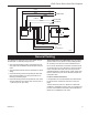
LDVR Series Direct Vent Gas Fireplace L1 BLACK L2 WHITE POWER CORD GREEN PURPLE PILOT SENSING CLEAR PILOT IGNITER YELLOW P O M O VALVE CIRCUIT BOARD BLUE ORANGE RED WHITE ON/OFF SWITCH OR WALL THERMOSTAT FP1571 Fig. 9 SIT822 Valve with Synetek electronic control wiring diagram. General Venting Your fireplace is approved to be vented either through FP1571 the side wall, or vertically through the roof.
LDVR Series Direct Vent Gas Fireplace General Venting Information - Termination Location INSIDE CORNER DETAIL G V H A N N D L V E C B V F B ����� ������ B V Ope Operable rable V B B B J X X AIR SUPPLY INLET M I A CFM145a V VENT TERMINATION V V Fixed Closed C = Clearance to permanently closed window D = Vertical clearance to ventilated soffit located above the terminal within a horizontal distance of 2’ (610mm) from the center line of the terminal E = Clearance to unventilated
LDVR Series Direct Vent Gas Fireplace Termination Clearances Termination clearances for buildings with combustible and noncombustible exteriors. Inside Corner Alcove Applications* Outside Corner G= Combustible 6" (152 mm) G F= Combustible 6" (152 mm) Noncombustible 2" (51 mm) V Noncombustible 2" (51 mm) V C V E O F Balcony with perpendicular side wall Balcony with no side wall D C E = Min. 6” (152 mm) for non-vinyl sidewalls Min. 12” (305 mm) for vinyl sidewalls O = 8’ (2.4 m) Min.
LDVR Series Direct Vent Gas Fireplace Twist Lock Pipes 30 When using CFM Corporation twist-lock pipe it is not necessary to use sealant on the joints. The only areas of the venting system that need to be sealed with high temperature silicone sealant are the sliding joints of any telescopic vent section used in the system.
LDVR Series Direct Vent Gas Fireplace Vent Opening for Combustible Wall 9³⁄₈” (240mm) 20" (508mm) Framing Detail 10³⁄₈” (264mm) Top View Straight Venting Fireplace Hearth DVR584-600 20" 20" Rear vent no elbows (508mm) (508mm) Max. Max. 2/99 djt Opening for Noncombustible Wall 7¹⁄₂” (190mm) VO584-100 45° 45° Fig. 15 Locate vent opening on wall. Max. Length 12” (305mm) Adjustable Zero Clearance Sleeve #8 Screws (2) Top View REAR VENT-TOP VIEW Rear Vent Corner Installation #8 Screws (2) Fig.
LDVR Series Direct Vent Gas Fireplace Zero Clearance Sleeve Termination Flex Section Appliance Collars Firestop CFM133 Fig. 17 Firestop and zero clearance sleeve in place. CFM133 DVR Series Typical corner install Finished Wall 2/26/01 sta Vent Termination FP1473 Fig. 19 Grasp the vent pipe close to the collar and bend to 45° angle. Do not exceed 45°. Rise FP1473 corner flex install 4/04 djt FP1472 Fig. 20 There must be a 1/2” rise per foot length. Vertical Sidewall Applications FP1005 Fig.
LDVR Series Direct Vent Gas Fireplace Horizontal plane means no vertical rise exists on this portion of the vent assembly. • The maximum horizontal vent run is 20 ft. (6.1 m) when the vertical vent rise is 7¹⁄₂ ft. (2.3 m). (Fig. 21) • The maximum number of 90° elbows per side wall installation is three (3). Vertical Dimension 7¹⁄₂’ Minimum When Horizontal Run is 20’ 7 ft. (2134 mm) 10 ft. (3048 mm) Maximum 20 ft. (6.1m) 12" (305mm) 90° Elbow = 3 ft. A + B = 17 ft. (Max.) 7 ft. 6 in. (2286 mm) 48" (1.
LDVR Series Direct Vent Gas Fireplace Vertical Sidewall Installation STEP 1 Locate vent opening on the wall. It may be necessary to first position the fireplace and measure to obtain hole location. Depending on whether the wall is combustible or noncombustible, cut opening to size. (Fig. 25) Adjustable Zero Clearance Sleeve #8 Screws (2) #8 Screws (2) For combustible walls first frame in opening. Combustible Walls (Fig. 25): Cut a 9³⁄₈”H x 9³⁄₈” W (240 x 240 mm) hole through the exterior wall and frame.
LDVR Series Direct Vent Gas Fireplace X X X Always install horizontal venting on a level plane. CFM138 CFM136 Fig. 28 Measure horizontal length including 2” overlap. CFM136 X length Rear Vent horizontal High 2/26/01 sta Temperature Sealant Fig. 30 Horizontal length requirement. CFM138 Below Grade 4", 7" collarInstallations 2/26/01 sta When it is not possible to meet the required vent terminal clearances of 12” (305 mm) above grade level a snorkel vent kit #7TDVSNORK is required.
LDVR Series Direct Vent Gas Fireplace Vertical Through-the-Roof Applications Zero Clearance Sleeve (if required) 7TDVSNORK (Snorkel) Firestop 4” (102mm) Clearance Min. 7” Pipe This Gas Fireplace has been approved for: 1. Vertical installations up to 40’ (12 m) in height. Up to 10’ (3 m) horizontal vent run can be installed within the vent system using a maximum of three 90° elbows.
LDVR Series Direct Vent Gas Fireplace Attic Insulation Shield Max. 8’ (2.4m) 45° 40’ (12m) Max. 8’ (2.4m) Joist Typical Ceiling Support Application Ceiling Installation 45° 11" 11" Upper Floor Joist Typical Roof Support Application Typical Offset Installation Firestop Spacer Nails (4) FP1021 Fig. 34 Typical vertical roof applications. FP1021 Vertical Through-the-Roof Installation Typical vertical through the roof 1. Locate your fireplace. application 2.
LDVR Series Direct Vent Gas Fireplace Vent Termination Roof Storm Collar 2’ Min. Roof Flashing Roof Support Attic Insulation 40’ Shield (12m) Attic Insulation Joists Min. 2' (610 mm) Joists FP1185 Fig. 38 Minimum termination to roof clearance. FP1022 Fig. 37 Typical straight-up installation.
LDVR Series Direct Vent Gas Fireplace Venting Components 7TDVRVT - Through the wall Rear Vent Termination 584A venting components rear vent term 4/6/99 djt 584B Vent components Starter Kit 2/25/99 djt 584C Vent components 584D 45 degree elbow Vent Components 2/25/99 90 degree djt elbow 584E 10/20/99djttwistlock 2/25/99 Venting Components 10/20/99 twist lock Telescope vent 584F 2/25/99 djt Venting Components 10/20/99 twist lock Pipe sections 2/25/99 djt 10/20/99 twist lock 584G Venting Components Firest
LDVR Series Direct Vent Gas Fireplace Operating Instructions Glass Information Only glass approved by CFM Corporation should be used on this fireplace. • The use of any non-approved replacement glass will • • • void all product warranties. Care must be taken to avoid breakage of the glass. Do not operate appliance with glass front removed, cracked or broken.
LDVR Series Direct Vent Gas Fireplace Installation of Logs, Lava Rock & Ember Material The logs are fragile and should be handled with care. Keep the packaging material out of the reach of children and dispose of the material in a safe manner. The individual logs can be easily identified by the numbers cast on the underside of each log.
LDVR Series Direct Vent Gas Fireplace 36LDVR 1. Place rear log (B135) on rear Rear (B135) bracket (ensure log is seated properly to the bracket and located to the two pins), so it will not move from side to side and is firmly positioned on the bracket. 2. Place front left log (B136). Use the log’s bottom hole to locate it onto the front support and just rest on top of the rear log. 3. Place front right log (B137).
LDVR Series Direct Vent Gas Fireplace 43LDVR 1. Place rear log (BD15) on rear bracket Top Center (BBD18) (ensure log is centered and seated Rear properly to the log support). (BD15) Front Right 2. Place front left log (BD16). Use log’s (BD17) bottom notch to locate it onto the front support and just rest on top of the Front Left burner housing tile. (BD16) 3. Place front right log (BD17). Use log’s bottom notch to locate it onto the front support and just rest on top of the burner housing. 4.
LDVR Series Direct Vent Gas Fireplace 33LDVR LG384 Glowing Embers 36LDVR LG385 LG384 33LDV log flames 1/05 Glowing Embers 39LDVR LG415 Glowing Embers ����� ���������������� 43LDVR ���� LG385 36LDV log flames 1/05 LG435 Glowing Embers Fig. 48 Correct burner flame appearance for the LDVR fireplaces.
LDVR Series Direct Vent Gas Fireplace Lighting and Operating Instructions FOR YOUR SAFETY READ BEFORE LIGHTING WARNING:If you do not follow these instructions exactly, a fire or explosion may result causing property damage, personal injury or loss of life. A. This heater has a pilot which must be lit manually. When lighting the pilot follow these instructions exactly. B. BEFORE LIGHTING smell all around the heater area for gas.
LDVR Series Direct Vent Gas Fireplace Lighting and Operating Instructions For Fireplaces equipped with SIT822 Gas Valve (EN or EP) Warning:If you do not follow these instructions exactly, a fire or explosion may result causing property damage, personal injury and loss of life. FOR YOUR SAFETY READ THE FOLLOWING WARNINGS BEFORE LIGHTING THE APPLIANCE A. This fireplace is equipped with an ignition device which automatically lights the pilot. DO NOT try to light the pilot by hand. B.
LDVR Series Direct Vent Gas Fireplace Troubleshooting - Honeywell Millivolt Valve Remove Window Frame Assembly Before Service Work CHECK Gas Supply On NO ▼ START • Supply Line Hooked Up • Shutoff Valve Open YES • Lockout Has Engaged. Wait 60 ▼ • NO ▼ Pilot Lights With Piezo Ignitor • • YES • For Air In The Lines • Thermopile Needs A Min. NO ▼ ▼ Pilot Stays Lit • • • • YES YES 325mv. Adjust Pilot Flame Height. All Wiring Connections Replace Thermopile Thermocouple Needs A Min.
LDVR Series Direct Vent Gas Fireplace Troubleshooting the Gas Control System SIT 822 Valve with Synetek Electronic Control Operating Diagram Normal Operation Abnormal Operation ON/OFF Switch Closed? 5 sec Inter-Trial Delay YES Safe Start Check On? NO YES LED: Steady Flash? Lockout: Flame detected out of sequence Reset by interrupting ON/OFF switch or power for 10 sec 0 Sec Purge LED: 5 Flashes? Reverse power cord polarity Ignition Trial: 30 sec Spark ON Pilot Valve ON.
LDVR Series Direct Vent Gas Fireplace 5. C OF IL FP � B D OF IL Natural Gas E FP 6. A O 2. 3. 4. OT 1. The procedure for converting from one gas to another is the same regardless of the initial gas used. The only variation is in the orifice sizes and component part numbers. Your authorized service provider will ensure the correct parts are used. Disconnect power to the unit and shut off the gas supply. Remove window frame assembly. Carefully remove the logs & lava rock material.
LDVR Series Direct Vent Gas Fireplace Regulator Cap Conversion Screw 12. After bleeding the gas line and checking for leaks with a soap solution, replace the window frame assembly. Fire up the unit, check for flame impingement on the logs, adjusting them if necessary. Check the manifold and supply pressures against the appliance specifications. Pressure Regulator Housing LO HV120 Fig. 51 Honeywell Gas Valve.
LDVR Series Direct Vent Gas Fireplace 1 1 33LDVR 36LDVR 1b 1f 1a 1h 1a 1b 1c 1a 1g 43LDVR 1d 1d 1d 1e 39LDVR 1 2 14 12 3 18a,b 11 9 7a,b 6a,b 19a,b 15 16 13 17 8 LO HI 21 1b 1c 1c 1i 1g 1a 20 23 26 30 29 31 36 24 22 25 33 34 32 35 37 39 40 41 42 43 CFM Corporation reserves the right to make changes in design, materials, specifications, prices and discontinue colors and products at any time, without notice.
LDVR Series Direct Vent Gas Fireplace LDVR Ref. 1. 1a. 1b. 1c. 1d. 1e. 1f. 1g. 1h. 1i. 2a. 2b. 3. 4a. 4b. 5a. 5b. 6a. 6b. 7a. 7b. 8. 9. 10. 11. 12. 13. 14. 15. 16. 17. 18a. 18b. 19a. 19b. 20. 21. 22. 23. 24. 25. 26. 29. 30. 31. 32. 33a. 33b.
LDVR Series Direct Vent Gas Fireplace LDVR Ref. 34. 35. 36. 37. 38. 39. 40. 41. 42. 43.
LDVR Series Direct Vent Gas Fireplace Optional Accessories Available Fan Kits Thermal Sensor Fan FK24 Fan Assembly This auxiliary fan system increases the efficiency of the circulation of the heated air. The FK24 fan kit allows variable speed control of the circulation fan and also incorporates a heat sensor in the circuit.
LDVR Series Direct Vent Gas Fireplace Wiring Instructions The fireplace, when installed, must be electrically connected and grounded in accordance with local codes or, in the absence of local codes, with the current CSA C22.1 Canadian Electric Code. Side Panel Back Panel For USA installations follow the local codes and the national electrical code ANSI/NFPA No. 70. Should this fan require servicing or repair the power supply must be disconnected. For rewiring of any replacement parts refer to Figure 53.
LDVR Series Direct Vent Gas Fireplace Screen Door Kit Optional Trim Kits Louvre Accent Trim Appliance Model Polished Brass 33LDVR 36LDVR 39LDVR 43LDVR Antique Brass 33LDVR 36LDVR 39LDVR 43LDVR Rustic Bronze 33LDVR 36LDVR 39LDVR 43LDVR Pewter 33LDVR 36LDVR 39LDVR 43LDVR Main Louvre Kit Additional Louvre 33DVLMP 36DVLMP 39DVLMP 43DVLMP 33DVLAP 36DVLAP 39DVLAP 43DVLAP 33DVLMA 36DVLMA 39DVLMA 43DVLMA 33DVLAA 36DVLAA 39DVLAA 43DVLAA 33DVLMR 36DVLMR 39DVLMR 43DVLMR 33DVLAR 36DVLAR 39DVLAR 43DVLAR 33DVLM
LIMITED LIFETIME WARRANTY LDVR Series Direct Vent Gas Fireplace PRODUCT COVERED BY THIS WARRANTY All Vermont Castings gas stoves, gas inserts, and gas fireplaces, and all Majestic or Northern Flame brand gas fireplaces equipped with an Insta-Flame Ceramic Burner, or standard steel tube burner.
Efficiency Ratings Model 33LDVRRN 33LDVRRP 33LDVREN 33LDVREP 36LDVRRN 36LDVRRP 36LDVREN 36LDVREP 39LDVRRN 39LDVRRP 39LDVREN 39LDVREP 43LDVRRN 43LDVRRP 43LDVREN 43LDVREP EnerGuide Ratings Fireplace Efficiency (%) 62.6 62.6 72.7 72.7 57.5 57.5 63.6 63.6 50.2 50.2 54.2 54.2 54.3 54.3 58.3 58.3 Steady State (%) Fan-OFF Fan-ON 81 82 82 83 81 82 82 83 81 82 82 83 81 82 82 83 76 79 79 80 78 79 79 80 77 78 78 79 77 78 78 79 CFM Corporation 2695 Meadowvale Blvd.