DV Power Vent System Model 7PDVS WARNING! IF THE INFORMATION IN THIS MANUAL IS NOT FOLLOWED EXACTLY, A FIRE OR EXPLOSION MAY RESULT CAUSING PROPERTY DAMAGE,PERSONAL INJURY OR LOSS OF LIFE. FOR YOUR SAFETY WHAT TO DO IF YOU SMELL GAS: • Do not try to light any appliance. • Do not touch any electric switch; do not use any phone in your building. • Extinguish all flames. • Immediately call your gas supplier from • your neighbours phone. Follow the gas suppliers instructions.
DV Power Vent System Table of Contents General Information .................................................................................................... 3 Power System Parts and Description ......................................................................... 4 Clearance to Combustibles ........................................................................................ 5 Restrictor Plate Orifice Size and Models Chart ..........................................................
DV Power Vent System General Information and Instructions for the DV-Power Vent System Model 7PDVS • This DV Power Vent System was designed to be used only on units with electronic ignition (EN or EP). • This DV Power Vent System was certified by CSA to be used only with CFM Corporation Direct Vent models, as listed in this manual.
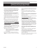
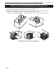
DV Power Vent System DV Power Vent System Parts and Description: 1. DV POWER VENT box assembled with a 6FT power cord. 2. Two deflectors to be added to the side wall vent termination. 3. Assorted restrictor orifice plates to be used according to the instructions for specific models. 4. Installation and Operating Instruction Manual.
DV Power Vent System Clearance to Combustible Materials and Access Door • The DV Power Vent System box needs a minimum 1” clearance all around the box. The DV Power Vent System box already has a 1” stand-off on all sides. • Pipes from the fireplace to the DV Power Vent System box and from the box to the vent termination need: • Clearance to combustible materials of 1” all around the pipe on vertical sections.
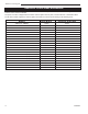
DV Power Vent System Restrictor Orifice Sizes and Models After you plan the venting lay-out and before the installation of the power vent box, check the following chart to make sure the correct orifice is installed. The power vent box is shipped with the 29/32” restrictor plate orifice in place, used for 36LDVT or 36LDVR models.
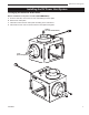
DV Power Vent System Installing the DV Power Vent System 1-Changing the Restrictor Orifice Plate: Before installation of the power vent box (RECOMMENDED): A. From the inlet side, remove the two 3/8” nuts holding the orifice plate. B. Remove the orifice plate. C. Install the correct restrictor orifice plate according to the chart above. D. Place back the two nuts to hold the restrictor orifice plate and tighten.
DV Power Vent System 2-Install the Vent Pipes and the DV Power Vent System Box: Install pipes and elbows according to the lay-out from the unit to the Power Vent System Box and from it to the vent termination. Follow the vent installation according to the fireplace manual recommendations. Remember that the blower shaft MUST ALWAYS BE in a horizontal plane and the pressure switch diaphragm MUST ALWAYS BE in a vertical plane with the hose connections pointing down.
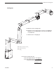
DV Power Vent System Venting Up: L6 L7 L5 L4 A - Maximum 40FT of straight pipe. B - Minimum 10FT of straight pipe for units up to 33,000BTU/h, Minimum 15FT of straight pipe for units from 33,000BTU/h to 40,000BTU/h. L3 C - Maximum 6FT of straight pipe.
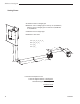
DV Power Vent System Venting Down: A - Maximum 40FT of straight pipe. B-Minimum 10FT of straight pipe for units up to 33,000BTU/h, Minimum 15FT of straight pipe for units from 33,000BTU/h to 40,000BTU/h. C-Maximum 6FT of straight pipe. L1 D-Maximum 12FT down.
DV Power Vent System 3- DV Power Vent System Setup: 3.1 - Checking the Pressure Switch Position: The pressure switch diaphragm must be in a vertical plane. The pressure switch hose connections should NEVER point up. The BEST position is pointing down, but can be pointed to the sides. Depending on the final location of the DV Power Vent System box, the pressure switch hose connection needs to be checked. If the hose connection position needs to be adjusted, follow these steps: 1.
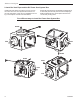
DV Power Vent System 3.3 - Adding Deflectors to the Side Wall Vent Termination: 1. Open the plastic bag and check all components. (One Top Deflector, one Bottom Deflector, four self-tapping screws) 2. Install the bottom deflector using two screws provided with the kit. Refer to Figure A. 3. Open the top screen and install the top deflector. Refer to Figure B. Attach the top deflector using two screws provided with the kit. 4.
DV Power Vent System Wiring Diagram (Honeywell Ignition Module) PILOT 12 3 4 5 6 8 9 Fireplace 120 VAC HOT GREEN TO WALL THERMOSTAT OR ON/OFF SWITCH Fireplace 1/4" QC TERMINAL 90fl FEMALE 24 VAC RET BLACK 40VA TRANSFORMER 1/4" QC TERMINAL 90fl FEMALE 24 VAC HOT 120 VAC RTN YELLOW BLACK GREEN ORANGE ORANGE & INSTALLED WIRES BLACK BLACK BLUE NOVA SIT 822 VALVE WHITE BLACK 18 AWS SOLID, LOW VOLTAGE MINIMUM INSULATION 2/64" FIELD SUPPLIED WIRE SPEC.
DV Power Vent System Wiring Diagram (Synetek Ignition Module) 120Vac Hot Fan Rtn 120Vac Rtn Key Fan Hot Flame Sense Chasis / Burner Ground LED 1/4” Male Tab 24Vac Hot (R) Key Thermostat (W) Pilot Valve Hot Main Valve Hot Pilot / Main Valve Rtn.
DV Power Vent System Operation of the DV Power Vent System Turn the switch ON/OFF or the wall thermostat, to the ON position. Blower will start immediately and will purge the unit and the vent system for 45 seconds. At that point, the pilot will light and the main burner(s) will follow. When the switch ON/OFF or the wall thermostat, is turned to OFF, the main burner and the pilot will shut-down immediately and the blower will run for 45 seconds to clear the flue gases before turning OFF.
DV Power Vent System Changing the Orifice Plate After the DV Power Vent Box is Installed If there is a need to change the restrictor plate orifice on the DV Power Vent System box, follow the steps below: A. Turn the power OFF to fireplace and power vent. B. Remove the blower’s cover (two parts): • • • • • • Remove the hose attached to the blower casing. Remove two screws. Refer to Figure A. Remove two nuts from the right side cover. Remove the right side cover by pulling it out. Refer to Figure B.
DV Power Vent System Screws Figure A Figure D Figure E Figure B Figure C Figure F 10003262 17
DV Power Vent System Troubleshooting the Power Vent System SIT 822 Valve with Honeywell Electronic Ignitor and Synetek Power Vent Board Service must be performed by a qualified installer, service agency or your gas supplier. BEFORE COMMENCING TO TROUBLE SHOOT THE UNIT: 1. Check if there is power to the unit (fireplace) and to the power vent box. 2. Check if there is gas to the unit (fireplace). 3.
DV Power Vent System Troubleshooting the Power Vent System SIT 822 Valve with Synetek Electronic Ignitor and Synetek Power Vent Board Service must be performed by a qualified installer, service agency or your gas supplier. BEFORE COMMENCING TO TROUBLE SHOOT THE UNIT: 1. Check if there is power to the unit (fireplace) and to the power vent box. 2. Check if there is gas to the unit (fireplace). 3.
DV Power Vent System 11 14 7 4 5 6 3 2 1 8 15 16 10 9 CFM Corporation reserves the right to make changes in design, materials, specifications, prices and discontinue colors and products at any time, without notice. 7PDVS DV Power Vent System Ref. 1. 2. 3. 4. 5. 6. 7. 8. 9. 10. 11. 12. 13. 14. 15. 16. 17. 18. 19.
DV Power Vent System 7PDVS DV Power Vent System Ref. 20. 21. 22. 23. 24. 25.
DV Power Vent System 22 10003262
DV Power Vent System 10003262 23
CFM Corporation 2695 Meadowvale Blvd. • Mississauga, Ontario, Canada L5N 8A3 800-668-5323 • www.cfmcorp.