EWF36A Fireplace Homeowner’s Installation and Operating Manual SAFETY NOTICE: IF5167 THIS APPLIANCE IS NOT PROPERLY INSTALLED, OPERATED AND MAINEPA36 TAINED, A HOUSE FIRE MAY RESULT. coverOF FIRE, FOLLOW THE INSTALLATION INSTRUCTIONS. FAILURE TO TO REDUCE THE RISK 3/02 FOLLOW INSTRUCTIONS MAY RESULT IN PROPERTY DAMAGE, BODILY INJURY OR EVEN DEATH. CONTACT LOCAL BUILDING OFFICIALS ABOUT RESTRICTIONS AND INSTALLATION INSPECTION REQUIREMENTS IN YOUR AREA.
Vermont Castings EWF36A Introduction Thank you for purchasing a Vermont Castings, EWF36A fireplace. An efficient fireplace carefully engineered to bring you the latest in wood combustion principles and modern foundry technology. You can count on years of comfortable heating and pleasurable fire viewing if you treat it properly and operate the EWF36A according to the directions in this owner’s guide.
Vermont Castings EWF36A Safety Information Please Read This Manual Before Installing and Using Fireplace IMPORTANT: Read all instructions and warnings carefully before starting installation. Failure to follow these instructions may result in a possible fire hazard and will void the warranty. Description The EWF36A fireplace is a solid fuel, woodburning, heat circulating fireplace.
Vermont Castings EWF36A Specifications EWF36A Range of heat output* ............... 11,300 - 75,500 Btu/hr Maximum heat output** ..... in excess of 100,000 Btu/hr EPA emissions rating (g/h, catalytic) .......................2.4* Area heated*** ............... Up to 2500 sq. ft. (558 sq. m) Size of wood splits .....................18” - 24” (450-610mm) Fuel Capacity ........................................... 40lbs. (18kg) Loading ..................................................................
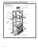
Vermont Castings EWF36A Chase Installation Insulation methods shown are optional for cold climate, not a requirement for unit operation. Termination Cap Storm Collar Pan Flashing Batt Insulation (cut out around firestop) Draftstop Firestop Ceiling Level Batt Insulation MUST be used in the Chase. Standoff Brick Ledge Outside Air Cover Plate Andiron Metal Safety Strips (1,2 or 3 pieces) FP554a Fig. 2 Fireplace and chase parts identification.
Vermont Castings EWF36A Chimney Requirements - Offset Installations Offset CHIMNEY FLUE EXIT Rise Chimney Section FP282 B A D E 6 FT. C G Rise Offset G 30° Offset Elbow H TCS8A Support 30° Return Elbow H 30° Offset Elbow B Hearth Floor Example 1 Example 2 Example 3 Notes: G + H cannot exceed 20 feet. Air Space Clearances: “S” Series (3-wall) = 2” Min.
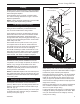
Vermont Castings EWF36A Planning Information Planning an installation is very important to ensure safety and to save time and money. An installer must predetermine where a fireplace will be set and how the chimney system will be run. NOTE: If installing the EWF36CFTK at a later date and if the hearth is being raised in front of the firepalce, the fireplace must be raised to the same height. Mounting the Fireplace The fireplace is shipped with lifting handles attached to each side with lifting straps.
Vermont Castings EWF36A Installation Chimney Supports The chimney system is supported by the fireplace for vertical chimney heights less than 30’ (9m) above the hearth. Chimney supports are required if the vertical height exceeds 30’ (9m). Locate chimney supports at ceiling holes or other structural framing at 30’ (9m) heights. Spacing between chimney supports must not exceed 30’ (9m). Use Chimney Support Model TCS8A. (NOTE: The TCS8A cannot be mounted directly to the fireplace.
Vermont Castings EWF36A Framing Framing can be constructed before or after the fireplace is set in place, however, most installers build the frame before setting the fireplace. Frame fireplace with 2 x 4 lumber or heavier materials. Refer to framing dimensions in Figure 1 for basic fireplace specifications. Chimney Centerline Actual Centerpoint 9���" (241mm) NOTE: Framing should be positioned to accommodate wall covering and fireplace facing material.
Vermont Castings EWF36A Ceiling Chimney Hole/ Possible Obstructions Existing Ceiling Joists 17¹⁄₂” (445mm) 17¹⁄₂” (445mm) The size of the hole in ceiling will vary with the angle at which the chimney passes through ceiling. Drive a nail up through ceiling at marked chimney center point. Go to floor above and see where hole will be cut. Check to see where existing ceiling joists and other possible obstructions are located...i.e. wiring, plumbing etc...
Vermont Castings EWF36A Nail Top Standoffs Nail Side Nailing Flanges Installation Instructions Determine the location of the fireplace as described in the fireplace Installation Manual. Then plan location of the duct termination and the route of the duct run between the fireplace and the duct termination. Duct run must be limited to a maximum distance of 40 feet from the fireplace pipe collar to duct termination. This will provide the least restriction to air flow. No more than four (4) 90° elbows can be used.
Vermont Castings EWF36A exposed when cover plate is removed. Retain for future use. 2. Slide the two (2) air duct assemblies provided with the unit into the openings on each side of the unit. (Fig. 14) 3. Attach the air duct assemblies to the inside panel with four (4) screws removed in Step 1. (fig. 14) Air Duct Assembly Installing the Chimney System Start by attaching the first chimney section to the collar on top of the fireplace. Install the pipe as pictured in Figure 16.
Vermont Castings EWF36A Canadian Requirements for Insulation Shield Installing the Firestop Spacer in the Ceiling Hole A firestop spacer is used to keep pipe spaced properly and required for safety. Nail the firestop spacer (at each corner) to the framing members of the ceiling hole. NOTE: A firestop spacer is not required at the roof. Hole sizes listed in Figure 9 for angled firestop spacers provide minimum required air space to chimney pipe for ceiling thickness up to 8” (203 mm).
Vermont Castings EWF36A Penetrating the Roof Run pipe to roofline. Since chimney system must be vented to the out-of-doors, you must use an approved CFM Corporation termination. If a chase is used, refer to the installation manual provided with the termination cap. Locate Chimney Centerpoint on Roof Use same procedure detailed in locating center point of the flue system. Drive a nail up through roof at the center point. This will determine center point on outside of the roof.
Vermont Castings EWF36A Finish Wall Finish the wall with material of your choice. Do not install a combustible mantel shelf less than 12” (305 mm) above the firebox grille opening. Do not install a mantel face plate less than 6” (159 mm) from top of grille opening. (Fig. 20) If a combustible material is used below a flat mantel shelf, consult your local building codes for minimum clearance from top of fireplace opening to bottom of mantel shelf.
Vermont Castings EWF36A Examples of wall shield insulation: Noncombustible material with a lower R value may be used, provided thickness of material is sufficiently greater to maintain an equivalent (total) thermal resistance (Rt). 1. Manville - CERAFORM 126, K=.27, 1/2 inches thick 2. EH2416, K = .458, 1 inch thick required. Example of Determining Hearth Extension Equivalents Hearth Installation A hearth extension is required to protect a combustible floor in front of the fireplace.
Vermont Castings EWF36A Minimum Hearth Extension Dimensions Minimum Wall Clearances WITH Noncombustible Surround Facing WITHOUT Noncombustible Surround Facing Shaded area starts 1/2" away from edge of unit 4" Brick (Example material) 4" E F** C** Firebox Opening E NOTE: No material may cover black cast face. Hearth extension must be flush with bottom of fireplace. H G G J D A - Min. clearance to combustible perpendicular wall B - Min.
Vermont Castings EWF36A Operation Attach Handles Primary Air Control Damper The fallaway handles are used to open and close the front doors. Remove after each use so they will not get hot. Keep in convenient location for each use. (Fig. 27) Assemble the primary air control and damper handles by passing the 3³⁄₈” screw through the ceramic shaft and into the bright metal hub. Tighten carefully until snug. Do not overtighten. Ceramic handle could crack. (Fig.
Vermont Castings EWF36A The Fan Heated air from the fireplace is forced into the room by an internal fan. The control for the fan is in the right corner of the unit. “Off” is to the far left. “High” is just to the right of “Off.” “Low” is to the far right. Variable adjustment of the fans is possible with any setting between “high” and “low.” For best results, coordinate fan speed with the setting of the primary air control. For example, when the air control lever is set at “low,” also set the fan at “low.
Vermont Castings EWF36A Starting and Maintaining a Wood Fire Burn solid wood fuel only in the EWF36A, and burn it directly on the grate. Do not elevate the fuel. Do not burn coal or other fuels. Minimize thermal stress by allowing the plates to adjust gradually during an initial break-in fire by following Steps 1-3 below. WARNING: Operate your EWF36A only with the doors fully closed.
Vermont Castings EWF36A Different results may be experienced even in the same installation if you switch from burning good, dry wood to wood that is partially rotted or inadequately seasoned. To compensate for these factors in cold climates, it may be necessary to operate the EWF36A with the air control set to a higher level more of the time. Remove and Store Ash Safely Check the ash pan before reloading the stove, and empty if necessary using the following procedure: • • • • • • Open the damper.
Vermont Castings EWF36A Maintenance Keep your EWF36A Fireplace Looking New and Working Its Best Care of the Cast Iron Surface An occasional dusting with a dry rag will keep the painted cast iron of your EWF36A fireplace looking new. If the paint needs retouching, first allow the surface to cool completely. Wire-brush areas needing to be painted. Touch-up with high temperature stove paint available from your local dealer. Apply the paint sparingly. Two light coats are better than one heavy one.
Vermont Castings EWF36A When to Suspect a Combustor Problem The best way to evaluate the performance of your EWF36A’s combustor is to observe the amount of smoke leaving the chimney - both when the combustor has “lighted-off” and when it has not. Follow these steps: Wedge (In Place) • With a fire going and the combustor properly activat- • ed, with the damper closed to route smoke through it as described in the Operation Section, go outside and observe the smoke leaving the chimney.
Vermont Castings EWF36A Replaceable Fiberglass Gaskets Gasket Size... 1/2” 5/8” 3/16” 1/2” 1/2” Braided ...And The Parts It Seals The door to the front Door to the hearth brick support The glass seal to the door Cat holder to top plate Damper to top plate Should you need to change a replaceable gasket, wait until the fire is out and the stove has cooled. Be sure to follow the standard safety procedure for working with dusty materials: Wear safety goggles and a dust mask.
Vermont Castings EWF36A The prefabricated chimney used with your fireplace should be cleaned from above using an 8” round brush and the appropriate number of extension rods for complete access. The chimney cap first must be removed following the procedure recommended by the manufacturer. After thoroughly cleaning the chimney, reinstall the chimney cap according to the manufacturer’s directions. Maintenance Schedule Fireplace: Daily: • Ash should be removed before the level reaches the top of the pan.
Vermont Castings EWF36A Chimney Components Component Chimney Support Firestop Attic Insulation Shield Traditional Top Housing Housing Extension Contemporary Chase Top Termination Contemporary Flashing Description Used to support chimney for each of 30’ vertical height and 6’ of angled chimney run Required at each floor level and attic on multi-story installation Used to prevent insulation from coming in contact with the chimney system.Required in Canada. Optional in U.S.
Vermont Castings EWF36A 1 4 EWF36CLK 5 64 63 3 65 EWF36CFTK 6 52 49 7 48 42 62 44 41 50 51 43 2 18 2 56 45 24 55 25 52 EWF36CLK 86 75 26 11 76 80 39 47 15 16 20 13 32 54 74 27 19 EWF36CLK 76 30 22 16 38 77 87 Oper ati 85 82 n 24 36 21 83 75 84 nge Ra 74 EWF36S g 14 10 80 EWF36CLK 13 35 12 25 26 15 34 28 88 24 73 33 31 79 9 17 29 79 74 47 40 46 67 69 25 84 85 68 23 26 53 74 37 83 82 81 78 70 24 71 25 26 5167
Vermont Castings EWF36A EWF36A Fireplace Ref. 22. 23. 24. 25. 26. 27. 28. 29. 30. 31. 32. 33. 34. 35. 36. 37. 38. 39. 40. 41. 42. 43. 44. 45. 46. 47. 48. 49. 50. 51. 52. 53. 54. 28 (continued) Description Glass Right Door - EPA Front Right, Door Handle Assy. Vert. Nickel Damper Steel Handle w/Screw Handle, Ceramic Blk 2.78 Lg Ov Hd Sl 1/4-20 x 3/375 Lg Linkage Assy.
Vermont Castings EWF36A Optional Accessories Fan Kit FK26 Fan Fan Heat Sensor (Snapstat) Electrical Box The FK26 fan helps distribute heated air from within the firebox out into the room. The fan is controlled by a snapstat that turns power on and off as the firebox temperature rises above and falls below a preset temperature. A rheostat provides for variable fan speeds. Specifications Fan Speed Switch (Rheostat) 115 Volt / 60Hz / .
Vermont Castings EWF36A 30 20005167
Vermont Castings EWF36A Warranty Limited 3 Year Warranty CFM Corporation warrants that this woodburning stove will be free of defects in material and workmanship for a period of three years from the date you receive it, except that the catalyst, thermostat assembly, handles, glass door panels, cement, and gasketing shall be warranted as described below. CFM Corporation will repair or replace, at its option, any part found to be defective upon inspection by a Vermont Castings, Authorized Dealer.
CFM Corporation 2695 Meadowvale Blvd. • Mississauga, Ontario, Canada L5N 8A3 800-668-5323 • www.cfmcorp.