Great Outdoors TM STAINLESS Assembly and Owner’s Manual Stainless Series Gas Grill ASSEMBLER / INSTALLER: Leave these instructions with the consumer. CONSUMER / USER: Read all of these instructions and keep them in a safe place for future reference. FOR YOUR SAFETY If you smell gas: 1 Shut off gas to the appliance. 2 Extinguish any open flame. 3 Open lid. 4 If odor continues, immediately call your gas supplier or fire department.
Statement of Commitment Congratulations and thank you for your purchase of your new Great Outdoors grill. We are pleased that you have recognized the value of the design, function, and quality of components used in this product. We believe it is among the finest on the market. We are committed to producing quality products that your family will enjoy for years to come.
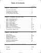
Table of Contents Page Number Chapter 1 - INSTALLATION 4 Necessary Information . . . . . . . . . . . . . . . . . . . . . . . . . . . Choosing a Safe Location . . . . . . . . . . . . . . . . . . . . . . . . . Liquid Propane Gas Grills . . . . . . . . . . . . . . . . . . . . . . . . . . L.P. Gas Dealer Instructions . . . . . . . . . . . . . . . . . . . . . . . Chapter 2 - ASSEMBLY INSTRUCTIONS 4 4 5-7 8 9 Step 1 ( Identifying Parts ) . . . . . . . . . . . . . . . . . . . . . . . . .
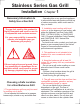
Stainless Series Gas Grill Installation Chapter 1 Necessary Information to Safely Use a Gas Grill · Operating this or any gas-fired appliance in an enclosed area can produce a build-up of carbon-monoxide, which could result in injury or death. 2. Installation must conform with local codes or, in the absence of local codes, with either the National Fuel Gas Code, ANSI Z223.1, NFPA 54 (USA), or CAN/CGA-B 149.2, Propane Installation Code (Canada) and CAN/CGA-B 149.1 Natural Gas Installation Code.
9. Make sure the heat shield and grease pan are in place under the grill bottom. · Heat and hot drippings from cooking food could damage the fuel supply system. IMPORTANT: NEVER leave a grill unattended when in use. Liquid Propane Gas Barbecue Grills WARNING: Do not use natural gas in an appliance designed for L.P. gas. Use only liquid propane (L.P.) gas in an appliance designed for L.P. gas. L.P. Gas Liquid Propane (abbreviated L.P.
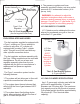
Burner FuelControl Valves Valve Orifice 4. The pressure regulator and hose assembly provided is factory set at an outlet pressure of 11 inches water column (.4 lb. per sq. Inch). Side Burner Control Valve WARNING: Any attempt to adjust the regulator is dangerous and could create a situation causing personal injury or property damage. Consult your L.P. gas dealer if you think the regulator is not working properly. Fuel Supply Hose Type 1 Fuel Regulator L.P. GAS SUPPLY CYLINDER L.P.
Have the gas dealer weigh the cylinder after filling to ensure that the cylinder is not overfilled. The L.P. cylinder must have a shut-off valve terminating in a Type 1 L.P. gas-cylindervalve outlet. A Type 1 compatible cylinder with a Type 1 cylinder valve has a positive seating connection that does not permit gas flow until a positive seal has been obtained. DANGER: a.) Do not store a spare L.P. gas cylinder under or near this appliance. b.) Never fill the gas cylinder beyond 80 percent full. c.
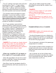
Take These Instructions to the L.P. Gas Dealer The L.P. gas cylinder has a Type 1 cylinder valve with a back-check module in its outlet that will not permit gas to flow until an evacuation device is installed. To purge the L.P. gas cylinder, the back-check module must be opened with an evacuation device. When using a cylinder exchange, be sure the exchanged cylinder is a Type 1 cylinder; a 510 POL cylinder will not fit a Type 1 regulator. FILLING AND PURGING TYPE 1 L.P.
Stainless Series Gas Grill Assembly Instructions Chapter 2 Getting Started Tools needed to assemble grill: 1. Please follow the steps in the order that they are presented. 2. Assemble the grill where you plan to use it. 3. You may want to place an old towel or cloth at the assembly site to prevent nuts and bolts from becoming lost. 4. For each step, loosely tighten all the fasteners before tightening them completely. 5. Have a friend help.
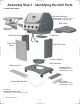
Assembly Step 1 - Identifying the Grill Parts Locate these parts: Grill Head Assembly KG432 Model: 4-Burner Unit (Shown) KG540 Model: 5-Burner Unit Side Table Side Burner Assembly Grease Pan Side Pillar Panel Front Pillar Panel Side Pillar Panel Cylinder Support Base Assembly Warming Rack Cooking Grids: KG432 Model: 4 pcs KG540 Model: 5 pcs Cylinder Retainer Wire Heat Tents: KG432 Model: 4 pcs KG540 Model: 5 pcs Not Pictured: master hardware pack (consisting of 1 each of A,B,C,D,E packs) L.P.
Assembly Step 2 - Assemble the Pillar Panels LOCATE THESE PARTS: Tools Needed: Phillips head screwdriver Front Pillar Panel (1) 10mm wrench USE HARDWARE PACK A : Lock Washer (6) Side Pillar Panel (2) M6x1 Nut (6) M6x1x10mm Bolt (6) Flat Washer (6) 1. Align one edge of the Front Pillar Panel with the corresponding edge of one Side Pillar Panel as shown. 2. For each mounting hole, insert a bolt and thread on a washer, lock washer, and nut as shown.
Assembly Step 3 - Assemble the Pillar to the Base Tools Needed: LOCATE THESE PARTS: Cylinder Support Phillips head screwdriver USE HARDWARE PACK B : Lock Washer (10) Base Assembly M6x1x16mm Bolt (10) Flat Washer (10) Rear of Grill Assembly 1. Set the Cylinder Support into the hole in the Base as shown with the notch toward the NOTE: For easier assembly, front. 2. Set the assembled Pillar panels onto the Base Assembly as shown. first loosely insert ALL of the screws before tightening them. 3.
Assembly Step 4 - Attach the Grill Head to the Pillar Tools Needed: LOCATE THESE PARTS: Phillips head screwdriver USE HARDWARE PACK C : Lock Washer (7) M6x1x16mm Bolt (7) Grill Head Assembly Flat Washer (7) 1. Set the Grill Head Assembly onto the top of the assembled Pillar and Base as shown. Ensure that the hose and regulator hanging from the bottom of the Grill Head are on the inside of the Pillar. 2. For each pre-threaded mounting hole, loosely insert a bolt, washer, and lock washer.
Assembly Step 5 - Attach the Side Tables Tools Needed: LOCATE THESE PARTS: Phillips head screwdriver USE HARDWARE PACK D : Lock Washer (8) M6x1x16mm Bolt (8) Side Burner Table Assembly Side Table Flat Washer (8) 1. Starting with the Side Burner Table Assembly, line up the mounting holes with the corresponding holes in the side of the Grill Head as shown. 2. For each pre-threaded mounting hole, insert a bolt, washer, and lock washer. 3. Firmly tighten the bolts. 4.
Assembly Step 6 - Mount the Side Burner Knob Tools Needed: USE HARDWARE PACK E : Burner Control Knob Phillips head screwdriver M4x0.7x8mm Bolt (1) M5x0.7x8mm Bolt (1) Match Holder and Chain 1. Working underneath the Side Burner Assembly, locate and remove the two bolts that are holding the brass burner to the side table. This will allow the burner tube to hang and move freely. 2. Locate the burner control valve attached to the end of the gas hose hanging from the side of the Grill Head Assembly. 3.
Assembly Step 6 - Continued 6. From the front side of the side table, insert and tighten the bolts from hardware pack E to the control valve as shown. There are 2 different sized bolts to ensure that the valve is properly oriented. 7. Press the knob onto the control valve stem as shown. Make sure the keyed shaft is properly seated - do not force the knob into place. 8. Find the single loose black igniter wire under the Grill Head Assembly, near where the side burner hose is ran through the collar.
Assembly Step 7 - Assemble Cooking Grids LOCATE THESE PARTS: Warming Rack Heat Tents (KG432 model: 4 pcs) (KG540 model: 5 pcs) Cooking Grids (KG432 model: 4 pcs) (KG540 model: 5 pcs) 1. Set the Heat Tents into the tub of the grill, one each directly above each burner. There are notches in the shelf to keep the Heat Tents in place. Make sure the slotted ends of the Heat Tents are towards the front of the grill. 2. Place the Cooking Grids on the upper shelf of the grill tub. One each above each burner. 3.
Assembly Step 8 - Grease Pan and L.P. Tank LOCATE THESE PARTS: L.P. Gas Cylinder (filled) Grease Pan Cylinder Retainer Wire 1. Place the Grease Pan underneath the Grill Tub from the back side as shown. There are brackets mounted to the underneath side of the tub to hold the Grease Pan in place.
Assembly Step 8 - Continued 2. Set the L.P. Gas Cylinder in the bottom of the grill from the back side. The bottom of the cylinder rests inside the hole in the grill base. 3. Insert the bent ends of the tank retainer wire into the retainer holes in the grill base as shown. 4. Lift the retainer wire up around the gas cylinder and lock it in place.
Connecting the L.P. Gas Cylinder Connecting the Regulator to Cylinder Tank collar omitted for clarity 1. The top knob on the supply cylinder must be closed. See that the top cylinder knob is turned clockwise to a full stop. NOTE: If you cannot complete the final connection, disconnect the regulator and repeat steps 4 through 6. If you are still unable to complete the connection, do not use this valve and regulator. 2. Check that all the grill burner knobs are turned off. 7.
Natural Gas Grills - Connecting to Natural Gas (for specially equipped natural gas grills only) DANGER: EXPLOSIVE AND FLAMMABLE! If the appliance is for connection to natural gas, the gas connections should be made by a qualified installer or a licensed plumber. The gas-supply line must not be installed by the consumer. A quick-connect coupling sleeve with 3/8” female end is provided. Install the connector socket at the pipe end, after the shut-off valve.
Natural Gas Grills - Connecting to Natural Gas (for specially equipped natural gas grills only) 5. Push the plug into the connector until the sleeve snaps forward to lock the fitting in place. Turn on the shut-off valve. The flow of gas to the appliance will be restricted if the plug is not connected properly. OPERATING THE QUICK-CONNECT Follow all directions on tags attached to hose. 1. To connect the fuel-supply hose to the fuel supply, the shut-off valve must be closed. 6.
Stainless Series Gas Grill Use and Care Directions Chapter 3 Leak Testing the Fuel Supply System Lighting Instructions Replacement Parts 23
Leak Testing DANGER To prevent fire or explosion hazard: · Do not smoke while performing a leak test. · Do not permit any sources of ignition in the area when testing for leaks. · Perform leak tests outdoors only. · Never perform a leak test near a fire or flame. Perform a leak test each time the gas supply cylinder is connected to the regulator. Leak test any time a part of the gas system is replaced. Perform a leak test at least once each year whether the L.P.
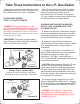
Lighting Instructions IGNITER LIGHTING SYSTEM CAUTION: Do not stand with head or arms over the grill. The Igniter System consists of an electronic igniter unit, individual burner-mounted ceramic electrodes, and lead wires. Gas is routed to the electrodes at each burner. When the igniter knob is pressed, an electric spark is created at the ceramic electrode. The gas is then ignited by the spark. To test: Watch the electrode tip inside the gas collector while activating the igniter.
Lighting Instructions MATCH LIGHTING Allow the grill to preheat with the grill lid closed for five to ten minutes before cooking. IMPORTANT: The match lighting holes are found under the side tables, in the side of the grill tub. When match lighting the grill, use the END gas control knob on the side you are using (closest to the match lighting hole). CAUTION: Do not touch any hot grill parts. The outside of the grill bottom becomes very hot during use. It may be necessary to use protective gloves.
Side Burner Operation To open the side burner, simply lift up and out on the side burner lid. The lid can be used as additional side table space. DO NOT place more than 10 pounds of weight on the side burner lid. DO NOT close the side burner lid while the side burner is on. The side burner table and lid may be very hot during and after use. Use caution when handling the components. LIGHTING INSTRUCTIONS 1. Open the side burner lid before operating. ! 2. Open the L.P. Gas Cylinder valve 1 to 1-1/2 turns.
Using Your Gas Grill TO BREAK IN A NEW GRILL CONTROL SETTINGS Before using it for the first time; operate the grill with lid closed on a low setting for about 30to 45 minutes to “season” the grill. This will help burn away oil and the smell of new paint. After the oil has burned away, check the burner flame. The high flame setting is for quick searing of meat. Sear foods, then finish cooking on a lower setting. A medium setting works best for cooking steaks, pork chops, and hamburgers.
Caring for Your Gas Grill COOKING TIPS CARING FOR YOUR GRILL Prior to lighting the grill, coat the cooking grids with cooking oil to prevent food from sticking. Preheat the grill with the lid closed about five to ten minutes before cooking. Cook with lid down when possible. This will keep temperature even, conserve fuel, improve food's flavor, and lessen flare-ups. Regular care of your grill will help keep it operating properly.
Cleaning and Maintenance Inspect and clean the burners regularly. Remove grill components from the grill bottom necessary to get to the burner inside. Use a wire bristle brush to clean the burner surface. A straightened paper clip is useful to remove debris or rust from the small burner ports. IMPORTANT! Make sure the valve orifices are inside burner tubes. Secure burner to the grill bottom, and reconnect the igniter wires. Replace all other parts inside grill. Reconnect the fuel cylinder to grill.
Stainless Series Replacement Parts Replacement parts are available direct from our warehouse. Some components are not available preassembled and may be ordered separately. For convenience, the following parts list is provided along with a representation of the items listed. Charges for replacement parts and shipping may apply. For warranty replacements, proof of ownership and date of purchase is required.
Outdoor Cooking Recipes Chapter 4 BEEF FLAVORFUL FLANK STEAK DISAPPEARING SHISH KEBOBS 1 beef flank steak (about 2 pounds) 3 tablespoons ketchup 1 tablespoon vegetable oil 1 tablespoon chopped onion 1 teaspoon brown sugar 1 teaspoon Worcestershire sauce 1 garlic clove, minced 1/8 teaspoon pepper 1/2 cup ketchup 1/2 cup sugar 1/2 cup soy sauce 1 teaspoon garlic powder 1 teaspoon ground ginger 2 pounds boneless beef sirloin steak (1-1/2 inches thick), cut into 1-1/2-inch cubes 1/2 fresh pineapple, trimmed
POULTRY PORK GRILLED CHICKEN BEST PORK RIBS 1 broiler/fryer chicken (3-1/2 to 4 pounds), quartered 1/4 cup vinegar 1/4 cup butter or margarine 1/4 cup water 1/4 teaspoon dried thyme 1/4 teaspoon oregano 1/4 teaspoon rosemary 1/4 teaspoon garlic powder 1/8 teaspoon salt 1/8 teaspoon pepper 3 pounds country-style pork ribs 1/2 teaspoon garlic salt 1/2 teaspoon pepper 1 cup ketchup 1/2 cup packed brown sugar 1/2 cup honey 1/4 cup spicy brown mustard 2 tablespoons Worcestershire sauce 1-1/2 teaspoons liqui
FISH / SEAFOOD SIDE DISHES SHRIMP COMBO PACKETS RICE ON THE SIDE 4 cups peeled potatoes (about 1-1/4 lbs.), sliced 1/8-inch thick 1 cup sliced leeks or mild onions 1 cup chopped plum tomatoes 20 jumbo shrimp (about 1 lb.
VEGETABLES DESSERTS ONION BLOOM CINNAMON APPLES 1 Bermuda onion 1 tablespoon butter 2 teaspoons honey 1/2 teaspoon Worcestershire sauce 4 medium tart apples, cored 4 teaspoons brown sugar 1/4 cup red-hot candies Vanilla ice cream, optional Peel onion; cut 1/2 -inch slice from top of onion and leave root end. Cut onion from top into 8 wedges to within 1/2-inch of root end. Gently pull wedges apart. Brush 12-inch square of heavy-duty aluminum foil with vegetable oil.
Manufacturer’s Limited Warranty The Great Outdoors grill is guaranteed against broken or damaged parts at the time of purchase. Components are guaranteed against defect as follows: All cast-aluminum and stainless steel panel parts are warranted against burn through and structural failure excluding paint, neglect, or abuse, for 75 years from the date of purchase. The stainless steel burners and the cast brass side burner have a limited pro-rated warranty of 10 years from date of purchase.