WARNING! IF THE INFORMATION IN THIS MANUAL IS NOT FOLLOWED EXACTLY, A FIRE OR EXPLOSION MAY RESULT CAUSING PROPERTY DAMAGE,PERSONAL INJURY OR LOSS OF LIFE. FOR YOUR SAFETY DIRECT VENT INSERT WHAT TO DO IF YOU SMELL GAS: MODEL * * * * Do not try to light any appliance. Do not touch any electric switch. Do not use any phone in your building. Immediately call your gas supplier from your neighbours phone. Follow the gas suppliers instructions.
TABLE OF CONTENTS Please read the Installation & Operating Instructions before using this appliance. Thank you and congratulations on your purchase of a Irving Oil fireplace. IMPORTANT - READ ALL INSTRUCTIONS AND WARNINGS CAREFULLY BEFORE STARTING INSTALLATION. FAILURE TO FOLLOW THESE INSTRUCTIONS MAY RESULT IN A POSSIBLE FIRE HAZARD AND WILL VOID THE MANUFACTURERS' WARRANTY. Installation Instructions ...........................................................................................................
INSTALLATION INSTRUCTIONS This gas appliance should be installed by a qualified installer in accordance with local building codes and with current CSA-B149.1 or .2 Installation codes for Gas Burning Appliances and Equipment. FOR U.S.A Installations follow local codes and/or the current National Fuel Gas Code. ANSI Z223.1. FOR SAFE INSTALLATION AND OPERATION OF YOUR IRVING OIL GAS FIREPLACE PLEASE NOTE THE FOLLOWING: 1 .
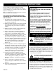
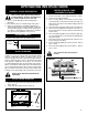
FIREPLACE & TRIM DIMENSIONS 3" (75mm) 1= 2= 3= 4= 5= SS or SSD Trim SL or SLD Trim SXL Trim BSL Trim BXL Trim R - Fireplace opening width Q - Fireplace opening height S - Depth of insert T - Firebox width at insert depth(S) U - Firebox depth at insert back height (V) V - Insert back height V Q T S R MINIMUM FIREPLACE INSERT OPENING T R I M F I R E P L A C E MO I P N E I N M I U N MG 10003929 U A1 B1 A2 B2 A3 B3 A4 B4 A5 B5 C D E F G H I J K Q R S T U V IRHEDV32 26 676 383/8" 975 29" 737 4115/16
GAS LINE INSTALLATIONGAS GAS SPECIFICATIONS MODEL FUEL RHEDV32RP Propane Gas GAS CONTROL MAX. INPUT B.T.U.H MIN. INPUT B.T.U.H. Millivolt Hi/Lo 27,000 20,250 This appliance may be installed in an aftermaket permanently located, manufactured (mobile) home, where not prohibited by local codes. When purging the gas line, the front glass must be removed. The gas pipeline can be brought into the fireplace base from the right side. It is most convenient to install it from the right side into the valve.
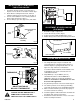
TH HONEYWELL VALVE INSTALLATION OF TRIM SWITCH FOR RP GAS VALVES PILOT ADJ TP TH TP 1. Thread wire through openings on the right side of fireplace. Do not cut wire or insulation on metal edges. 2. Slide switch assembly from the back, between subframe and trim, then fasten the screw. (Fig. 3) 3. For left side installation reverse switch position in bracket and repeat Step 2 (Fig. 4 ). 4. Connect wiring to gas valve (Fig. 5a & b) and switch. Fig.
LINER INSTALLATION - Fig. 6 The collar extending down from the termination base is the air intake connector. Be sure the flex vent, which is connected to this collar, is also connected to the labelled air intake flue collar on the fireplace. Make sure the Flex vent is attached on the correct collar and cap for exhaust as well. Slide the insulation provided in the termination kit over the two (2) 3" flex liners, (to be attached to the 3" Flue collar and cap of the termination).
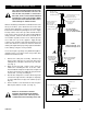
FAN KIT 3" FLEX VENT TWO PIECES DAMPER CLAMPS & SCREW FASTENER PLATE GASKET FLUE COLLAR PLATE FIG.2 UNIT 115 volt, 60 Hz.56W The fan kit includes the following: fan, temperature sensor, speed control and a 6 ft. cord. The following explains how to start and set the fan for automatic operation. 1. Plug in the electrical cord. 2. Start gas fire - see lighting procedures. 3. Turn on fan speed control. 4.
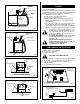
OPERATING INSTRUCTIONS GENERAL GLASS INFORMATION Only ceramic glass approved by Vermont Castings Majestic Products Company may be used for replacement on this unit. 1. The use of substitute glass will void all product warranties. 2. Care must be taken to avoid breakage of the glass. 3. Under no circumstances should this appliance be operated without glass properly installed, or with any cracked or broken glass.
LARGE LAVA ROCK PLACEMENT The large lava rock provided with this fireplace must be placed on the firebox base on either side of the burner assembly. Under no circumstances should these lava rock be placed on top of the burner assembly. CERAMIC REFRACTORY INSTALLATION 1. 2. 3. Remove front glass. Remove logs from unit. Remove refractory from package MAINTENANCE a. It is important to keep the burner and the burner compartment clean. This must be done periodically, at least once per season.
FLAME ADJUSTMENT FLAME CHARACTERISTICS Flame adjustment is accomplished by rotating the Hi/Lo adjustment knob located near the centre of the gas control. (Fig. 18) HI Turn counterclockwise to increase flame height. Honeywell Valve I L Turn counterclockwise to decrease flame height. SIT Pilot 3/8" - 1/2" LO O H SIT Valve Turn clockwise to lower flame height. It is important to periodically perform a visual check of the pilot and the burner flames.
LIGHTING AND OPERATING INSTRUCTIONS FOR YOUR SAFETY READ BEFORE LIGHTING WARNING: If you do not follow these instructions exactly, a fire or explosion may result causing property damage, personal injury or loss of life. A. This fireplace has a pilot which must be lit manually. When lighting the pilot follow these instructions exactly. B. BEFORE LIGHTING smell all around the fireplace area for gas. Be sure to smell next to the floor because some gas is heavier than air and will settle on the floor.
TROUBLE SHOOTING THE GAS CONTROL SYSTEM SIT 820 MILLIVOLT VALVE Note: Before trouble shooting the gas control system, be sure external gas shut off is in the "On" position. WARNING: BEFORE DOING ANY GAS CONTROL SERVICE WORK, REMOVE GLASS FRONT. SYMPTOM 1. Spark ignitor will not light 2. Pilot will not stay lit after carefully following lighting instructions. 3. Pilot burning, no gas to burner, Valve knob "ON", Wall Switch "ON". 4. Frequent pilot outage problem.
TROUBLE SHOOTING THE GAS CONTROL SYSTEM HONEYWELL MILLIVOLT VALVE START CHECK • GAS SUPPLY ON NO YES PILOT LIGHTS WITH PIEZO IGNITOR NO YES PILOT STAYS LIT YES • LOCKOUT HAS ENGAGED. WAIT 60 SECONDS AND TRY AGAIN. • FOR SPARK AT ELECTRODE WHILE DEPRESSING PIEZO — 1/8" GAP TO PILOT HOOD NEEDED. • ALL WIRING CONNECTIONS • REPLACE PIEZO IGNITOR NO • FOR AIR IN THE LINES • THERMOPILE NEEDS A MINIMUM 325mV. ADJUST PILOT FLAME HEIGHT. • ALL WIRING CONNECTIONS.
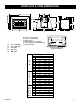
REPLACEMENT PARTS 35 10a/b 12 19 18 30 15 16 31 14 24 20 8 a/b 32 11 a/b 28 25 27 9 a/b 13 18 34 29 2 17 26 3 21 33 OFF O H PILOT ADJ ON P IL L I O T 22 23 a/b IRHEDV32 10003929 15
REPLACEMENT PARTS LIST Description 1 1a 1b 1c 1d 1e 1f 2 3 4a 4b 5 6a 6b 7a 7b 8a 8b 9a 9b 10a 10b 11a 11b 12 13 14 15 16 17 18 19 20 21 22a 22b 23a 23b 24a 24b 25 26 27 28 29 30 31 32 33 34 35 10003929 Log Set Complete Log Ember Front Log Front Left Log Front Right Log Rear Log Top Left Log Top Right Lava Rock (Package) Burner Lava Rock (Package) Burner Complete With Tiles (Nat.) Burner Complete With Tiles (Prop.) Ceramic Tile (Single) Orfice Front Burner (Nat.) Orfice Front Burner (Prop.
A-TRIM OPTIONS FOR RHEDV32 IMPORTANT: Only Trim Panel Assemblies approved by Vermont Castings Majestic Products Company can be used. A1) RHESS, RHESL, RHESSD, RHESLD & RHESXL TRIMS FRAME ASSEMBLY RHESS, RHESL, RHESSD, RHESLD and RHESXL 1. Lay Trim Top Facing and Trim Side Facings, face down on to an even surface such as a table or floor. Be sure not to scratch the painted surfaces. 2. Install the nuts and bolts (Fig. 21). Trim Top Deflector Trim Frame Top Section Side View 10/24 SCREWS Fig.
FRAME MOUNTING GENERAL INFORMATION The Decorative Front Frame should be installed last after all other work, such as gas connections, venting, etc., has been completed and thoroughly checked and tested for operation, leaks and proper installations requirements. Fit Decorative Frame to the fireplace and fasten (Fig. 25). SCREWS AS SHOWN FROM FRONT Fig. 25 Plastic on the trim must be removed before mounting onto the fireplace.
TRIM REPLACEMENT PARTS LIST All repair parts will be available from your local dealer.
A2) RHEBSL & RHEBXL TRIMS RHEBXL TRIM ASSEMBLY To install the kit you do not have to remove any piece of brass, you just add the external pieces. RHEBSL 1. Install trim channels (left and right sides). Use two screws to assemble each piece. 2. Slide on the trim top channel and fasten it from the back side. 3. Install the trim top deflector and use two screws to fasten it. (Fig. 26) 4. Remove ALL plastic protective covering from brass trim. Remove the frame trim from the unit if it is already installed.
A3) RHEFA and RHEFP TRIMS TRIM ASSEMBLY 3. Install bottom decorative plate by simply sliding it under the unit floor. No fastening is required for this installation (See Fig. 45). Be sure to remove protective cover. 4. Install the bottom louvre assembly by fastening the hinges with four screws to the pre-punched holes in the cabinet. 5. Re-install the front glass. 6. Install the top louvre by using the hooks to hang it in place. 1. Remove the front glass (see "Glass Frame Removal" section). 2.
A4) HEBTKP, HESBTKP, HECBTK, HECBTKMB & HEBTA TRIMS HECBTK HECBKMB HESBTKP HEBTKP - Cast bay window and grills in classic black trim kit Cast bay window and grills in midnight black porcelain enamel trim kit Steel bay window with polished brass and cast grills in classic black trim kit Steel bay window and bay louvres with polished brass trim kit Install the bay window after all other installation work has been completed, thoroughly checked, and tested for operation, leaks and proper installation require
HEBTKP Trim Assembly 1) Reposition controls. a) Remove the Fan Speed Control Box (Fig. 33). b) Attach the Fan Speed Control Box to the Bracket (Fig. 34) and install the Bracket into the Cabinet. Only for RN/RP VALVE units. c) Install the Control Knobs Extensions onto the appropriate Control Valve Knobs (Fig. 34). On units fitted with a Honeywell brand control valve the location of the control knobs and the ignitor button may vary slightly from those shown in Fig. 35.
Fig. 37. Hang the Window Grille or the Steel Frame onto the lower tabs of the Hanging Brackets. Fig. 38. Engage the slots in the Upper Grille Top Louvre with the upper tabs of the Hanging Brackets. Fig. 39. Attach magnets and brass trim to the steel frame. Fig. 40. Bracket for HEBTKP.
TRIM REPLACEMENT PARTS LIST IMPORTANT: Only Trim Panel Assemblies Approved by Vermont Castings Majestic Products Company Can Be Used on These Products. ALL repair parts will be available from your local dealer.
A5) CAST TRIM OPTIONS Cast Surround And HECBL HECBLUE HECCG HECGR CSSP CSLP Flat Face Cast Surround Black Cast Surround Blue Cast Surround Charcoal Grey Cast Surround Green Polished Brass Small Trim for Cast Surround Polished Brass Large Trim for Cast Surround (to be used with CSSP) A6) FREESTANDING KITS Convert Insert Into a Freestanding Stove Note: 1) Requires Bay Window Face Kit 2) Vent starter kit FSHEDVSK must be installed to use any of the freestanding shells.
VENTING COMPONENTS 8" x 12" VENT TERMINATION KIT Model: HEDVT (8" x 12") B (Fit Typical 8" x 12" and 9" x 13" flue Tile) A C HIGH TEMPERATURE SEALANT D Kit Includes: A - 8" x 12" Vent Termination (x1) B - Stainless Steel Clamps 3"-3.5" (x4) C - Hardware Package (x1) D - High Temperature Sealant (x1) 12" x 12" VENT TERMINATION KIT Model: HEDVT (12" x 12") B (Fit Typical 12"-13" x 12"-13" Flue Tile) A C HIGH TEMPERATURE SEALANT D FLEX VENT 25 FT.