
User's Manual


24
Stardance Direct Vent - Rear Vent Gas Heaters
20012950
Supporting DIRECT-TEMP: Horizontal Support
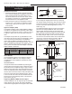
Horizontal runs of Direct-Temp should be supported
every 4’ (122 cm) of pipe. This can be done with the use
of plumbers strapping or the offset support.
Adjustable Length (AJ)
An Adjustable Length is available to accommodate
installations where non-standard lengths are necessary.
The adjustable length telescopes down over a standard
length of pipe and provides an extension range of 3¹⁄₂”
(89 mm) to 10¹⁄₂” (267 mm). Install by sliding the inlet
end of the adjustable length over the outlet end of a
standard length of pipe. After positioning the adjustable
length appropriately, secure it to the standard length
with two (2) #8 x1/4” sheet metal screws (provided).
Seal the area between both the top and bottom of the
adjustable length outer wall and the outer wall of the
standard length with an approved silicone sealant.
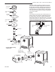
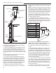
Fire Stopping
DIRECT-TEMP must be firestopped wherever it passes
through floors, ceiling or walls. The only location where
a firestop is not required is at the roof level. Both verti-
cal support components with trim plates provide for
firestopping. The wall thimble also acts as a firestop.
at other locations, a firestop spacer (FS) should be in-
stalled. In the attic the firestop should be placed on top
of the joist framing to prevent debris from falling into the
joist framing. (Fig. 41)
Firestop (FS)
Placed on Top
of Framed
Opening
Attic Framing
(No floor)
Maintain at Least
Minimum Clearance to
Combustibles, Wire and
Insulation
ST928
Fig. 41 Firestop spacer.
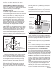
Horizontal Installation
1. Determine the appliance location. Refer to the appli-
ance manufacturer’s installation instructions for clear-
ance to combustible requirements, termination options,
number of elbows, maximum length, etc. Then posi-
tion the appliance and plan vent routing accordingly.
Consider locating the appliance in a place where there
will be no interference with wall studs, electrical wir-
ing, conduit, plumbing pipe or other obstructions. The
termination should be located at least 12” (305 mm)
(Fig. 42) above grade, remain above the snow line in
geographical areas that accumulate snow and be away
from traffic areas such as walkways if it is less than 7’
(2.1 m) high. Refer to Pages 10, 11, Figures 11, 12 for
more detail.
2. Assemble the pipe (and elbow if using) and attach it
to the appliance. Plan for a level to 1/4” per foot rise (6
mm per 305 mm) (from inlet to outlet) in the horizontal
system if not specified by the appliance manufacturer.
Horizontal runs should be supported every 4’ (122 cm).
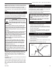
Snorkel Termination
Window Well
12” (305 mm) Minimum
Clearance Above Grade Level to
Air Intake
Grade Level
Sloped Away
From Building
Adequate
Drainage as per
Local Codes
Maintain 2”
(51 mm)
Clearance
Below Snorkel
ST929
Fig. 42 Below grade installation.
3.
Push the appliance near the desired location. Deter-
mine the centerpoint of the penetration by locating the
centerline of the outlet of the pipe with respect to the wall.
4. Frame an opening to the dimension specified in the
Framing Dimension Table 1. Ensure the centerline of
the pipe lines up with the center of the prepared open-
ing unless otherwise specified by the appliance manu-
facturer.
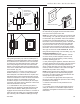
NOTE: As a general rule, the wall thimble is optional in
the U.S. However, there may be some manufacturers
that require it. Contact the appliance manufacturer for
information if uncertain. When installed in Canada, a
wall thimble is required on all installations in which
the vent passes through a combustible wall.
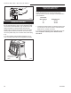
5. If required, install the outside half of the wall thimble
(WT) through the opening and screw or nail in place. (Fig.
43) Seal around the perimeter of the thimble face plate on
the exterior wall using an RTV silicone sealant to provide
protection from possible rain infiltration. (Fig. 43)
NOTE: The wall thimble accommodates wall thickness-
es of 4¹⁄₂” (114 mm) to 7¹⁄₂” (191 mm). If a larger range
is needed due to a thicker wall, it is permissible to field
fabricate a metal sleeve extension and attach it to the
shields.
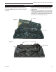
6. Install the horizontal termination to the exterior wall
using four (4) all purpose screws through the holes
located at each corner of the termination. Make sure
the arrow (embossed on the front of the termination)
is pointing up. (Fig. 44) If the house has vinyl siding,