INSTALLER / CONSUMER SAFETY INFORMATION PLEASE READ THIS MANUAL BEFORE INSTALLING AND USING APPLIANCE. WARNING! IF THE INFORMATION IN THIS MANUAL IS NOT FOLLOWED EXACTLY, A FIRE OR EXPLOSION MAY RESULT CAUSING PROPERTY DAMAGE, PERSONAL INJURY OR LOSS OF LIFE. FOR YOUR SAFETY Installation and service must be performed by a qualified installer, service agency or the gas suppler.
Stardance Direct Vent/Natural Vent Gas Heater Table of Contents PLEASE READ THE INSTALLATION & OPERATING INSTRUCTIONS BEFORE USING APPLIANCE. Thank you and congratulations on your purchase of a Vermont Castings stove. IMPORTANT: Read all instructions and warnings carefully before starting installation. Failure to follow these instructions may result in a possible fire hazard and will void the warranty. Installation & Operating Instructions General Information ...............................................
Stardance Direct Vent/Natural Vent Gas Heater General Information The Stardance Direct Vent/Natural Vent Room Heater, Model Nos. SDDVTCB, SDDVTEB, SDDVTMB, SDDVTBS, SDDVTCH, SDDVTVG, SDDVTBD, SDDVTCCB, SDDVTCEB, SDDVTCMB, SDDVTCBS, SDDVTCCH, SDDVTCVG, SDDVTCCBD, is a vented gas appliance listed to the ANSI standard Z21.88-2005 and CSA-2.33-2005 for Vented Room Heaters, and CSA 2.17M91, Gas-Fired Appliances For Use at High Altitudes.
Stardance Direct Vent/Natural Vent Gas Heater Installation Requirements Requirements for the Commonwealth of Massachusetts All gas fitting and installation of this heater shall only be done by a licensed gas fitter or licensed plumber.
Stardance Direct Vent/Natural Vent Gas Heater Stardance Direct Vent / Natural Vent Dimensions 7" Outer Dia. (178 mm) Supply Inlet 12���” (321 mm) Flue Collar C L 2���” (73 mm) 9" (229 mm) 12���” (321 mm) C L 7" Outer Dia. (178 mm) Supply Inlet 2���” (73 mm) 8" (203 mm) Flue Collar CL SDDVT Models 8���" (222 mm) SDDVTC Models 26���" (680 mm) 7���” (197 mm) Supply Inlet CL 3" (76 mm) 14���" (355 mm) 25���" (654 mm) Fig. 1 Stardance dimensions.
Stardance Direct Vent/Natural Vent Gas Heater Installation Requirements The installation must conform with local codes or, in the absence of local codes, with the National Fuel Gas Code, ANSI Z223.1/NFPA 54 - latest edition. (EXCEPTION: Do not derate this appliance for altitude. Maintain the manifold pressure at 3.5 inches w.c. for Natural Gas, and 10 inches w.c. for Propane). In Canada, installation must be in accordance with the current CSA B-149.1 Installation Codes and/or local codes.
Stardance Direct Vent/Natural Vent Gas Heater Parallel Installation: Minimum Clearance and Flue Centerline, Direct Vent and Natural Vent Wall Centerline from Floor Direct Vent Only C L C A D A C L B ST131b ST128b Stove Clearances: A: 4” (102 mm) B: 4” (102 mm) Pipe Centerlines: C: 15¹⁄₂” (395 mm) ST128b D: 9” (229 mm) Fig. 3 Parallel installation, minimum back and side clearStardance ances, and flue centerlines.
Stardance Direct Vent/Natural Vent Gas Heater Gas Specifications Model SDDVT Series SDDVT Series SDDVTC Series SDDVTC Series Max. Input Fuel Gas Control BTU/h Nat Millivolt 28,000 Prop Millivolt 28,000 Nat Comfort Control 28,000 Prop Comfort Control 28,000 Min. Input BTU/h 20,000 20,000 22,000 22,000 Air Shutter Setting Minimum rear injector air inlet openings. Model Natural Gas LP Direct Vent 1/2” Open 1/2” Open Natural Vent 1/2” Open 1/2” Open Weight: Fully assembled; 202 lbs.
Stardance Direct Vent/Natural Vent Gas Heater Restrictor Plate Adjustment for Extended Pipe Runs Vertical Termination - Direct Vent ONLY A vertical vent system must terminate no less than 8’ (2.44m) and no more than 40’ (12m) above the appliance flue collar. A restrictor plate (supplied) must be used where specified in all vertically terminated vent systems. (Fig. 8) NOTE: The restrictor plate supplied with the vertical termination should be discarded.
Stardance Direct Vent/Natural Vent Gas Heater Vent Termination Clearances When planning the installation, consider the location of the vent terminal and clearances. Some of the most common clearances to keep in mind are shown in Figure 11. Important: All vent clearances must be maintained. Check your vent termination clearances against Figures 11 through 13. The vent should be placed so that people cannot be burned by accidentally touching the vent surfaces when the stove is operating.
Stardance Direct Vent/Natural Vent Gas Heater General Venting Information - Termination Location INSIDE CORNER DETAIL G V H A N N D L V E C B V F B ����� ������ Ope V B V Operable rable B B V B J X X AIR SUPPLY INLET M I A CFM145a V VENT TERMINATION V Fixed Closed V K X AREA WHERE TERMINAL IS NOT PERMITTED Canadian Installations1 US Installations2 A = Clearance above grade, veranda, porch, deck, or balcony B = Clearance to window or door that may be opened 12” CFM145a (
Stardance Direct Vent/Natural Vent Gas Heater Termination Clearances Termination clearances for buildings with combustible and noncombustible exteriors. Inside Corner Alcove Applications* Outside Corner G= Combustible 6" (152 mm) G F= Combustible 6" (152 mm) Noncombustible 2" (51 mm) V Noncombustible 2" (51 mm) V C V E O F Balcony with perpendicular side wall Balcony with no side wall D C E = Min. 6” (152 mm) for non-vinyl sidewalls Min. 12” (305 mm) for vinyl sidewalls O = 8’ (2.4 m) Min.
Stardance Direct Vent/Natural Vent Gas Heater Venting Requirements and Options Direct Vent ONLY Approved Vent System Components The Stardance Heater must be vented to the outdoors through an adjacent exterior wall or through the roof. The venting system must be comprised of the appropriate listed venting components specified on this page. These parts are available from DuraVent Corporation, Selkirk Corporation or your Vermont Castings Dealer.
Stardance Direct Vent/Natural Vent Gas Heater CFM Vent Components The following kits are available to meet the needs of most installations. All pipe has a 7” outer diameter and includes a 4” diameter inner section. A (CG) designation indicates the part is finished in Charcoal Gray paint. Consult your dealer about other vent parts that may be appropriate to complete the installation. Min.
Stardance Direct Vent/Natural Vent Gas Heater Install the Optional Fan If you are installing the optional convection Fan Kit #2767 (FK26), continue here. If you are not installing a Fan Kit, go to Page 16, Venting System Assembly. 1. The fan kit includes a Blower Assembly and a Rheostat Assembly, connected by a cable. (Fig. 14) The Blower Assembly mounts to the bottom rear of the stove, and the Rheostat mounts to the valve bracket to the left of the valve.
Stardance Direct Vent/Natural Vent Gas Heater Venting System Assemlby - Direct Vent General Information The Stardance is approved for installation only with the vent components listed on Pages 13 & 14. Follow the vent component instructions exactly. For U.S. installations: The venting system must conform with local codes and/or the current National Fuel Gas Code, ANSI Z223.1/NFPA 54. E CEM NT For Canadian installations: The venting system must conform to the current CSA B149.1 installation code.
Stardance Direct Vent/Natural Vent Gas Heater Secure with a minimum of two #8 x 1/4” sheet metal screws and seal with hi-temp silicone. Inner Adapter Pipe 1/4-20 x 3/8 Phillips Screws For units factory equipped with appliance adapters from other brands of Direct Vent systems, it is permissible to simply slide a length of DT pipe over the appliance adapter. Secure with a minimum of two #8 x 1/4” sheet metal screws and seal with hi-temp silicone. ENT CEM Side Wall Termination Assembly ST355b Fig.
Stardance Direct Vent/Natural Vent Gas Heater 12” (305 mm) Max. Length Sleeve X #8 Sheet Metal Screws ST215 Fig. 26 Measure the horizontal length. Firestop ZCS103 Fig. 24 Assemble the wall sleeve and firestop. including a 2”ZCS103 overlap at the joint. (Fig. 25) use a hacksaw or tin snips to trim the pipe as needed. Zero Clearance Sleeve Firestop 5. Install first the&inner then the outer straight pipe 12/6/99end djtdown, to the point of the elsection(s), trimmed bow.
Stardance Direct Vent/Natural Vent Gas Heater Vent Termination Below Grade Recessed Wall Install Snorkel Kit #7FSDVSKS when it is not possible to meet the required vent termination clearances of 12” (305 mm) above grade level. The snorkel kit will allow installation depth of down to 7” (178 mm) below grade level. The seven inches is measured from the center of the horizontal vent pipe as it penetrates the wall.
Stardance Direct Vent/Natural Vent Gas Heater #7DVAIS Attic Insulation Shield Selkirk Direct-Temp Metalbestos Direct Vent System Installation Instructions #7DVFS Firestop in Upper Floor Use Four 8dNails #7DVFS Firestop in Ceiling ST222 Fig. 31 Install firestops and attic insulation shield. Use three #5 sheet metal screws at each joint ST222 vent thru ceiling 12/99 Sealant Storm Collar Upper edge of flange goes under upper shingles Flashing #7DVSKV (A, B, or F) RoofSupport ST221 Fig.
Stardance Direct Vent/Natural Vent Gas Heater Gasket Outlet End Inlet End Lock Tab To Termination To Appliance ST922 Fig. 33 Joint connection.
Stardance Direct Vent/Natural Vent Gas Heater Supporting DIRECT-TEMP: Vertical Support Vertical installations can be supported by two methods: Ceiling Support (CS) (used in flat ceiling installation) comes with a support plate and a support collar. Install it by screwing the support plate to the top of the properly framed ceiling joist opening, using screws provided. A round trim plate (TP) is attached to the ceiling, using screws, to provide a finished appearance once installed. (Fig.
Stardance Direct Vent/Natural Vent Gas Heater Firestop (FS) Placed on Top of Framed Opening Maintain at Least Minimum Clearance to Combustibles, Wire and Insulation Attic Framing (No floor) NOTE: As a general rule, the wall thimble is optional in the U.S. However, there may be some manufacturers that require it. Contact the appliance manufacturer for information if uncertain. When installed in Canada, a wall thimble is required on all installations in which the vent passes through a combustible wall. 5.
Stardance Direct Vent/Natural Vent Gas Heater Horizontal Termination Vertical Termination Storm Collar Approved Silicone Sealant Here Flashing Offset Support Collar ST931 Fig. 41 Horizontal termination. Firestop Spacer Vinyl Siding Standoff ����� ������������������������� ���� Horizontal Termination ST932 Ceiling Support Plate Ceiling Support Collar Fig. 42 Vinyl siding standoff and horizontal termination. 7.
Stardance Direct Vent/Natural Vent Gas Heater 6. Install the ceiling support cathedral ceiling support box assembly, as appropriate. 7. Determine the distance from the appliance outlet to a point just above [approximately 12” (305 mm) to 24” (610 mm)] either the cathedral ceiling support box or the ceiling support plate and assemble lengths of pipe to satisfy this distance. Do not attach assembly to appliance. 8. Loosely position the support collar around the assembled lengths (flared end down). 9.
Stardance Direct Vent/Natural Vent Gas Heater For U.S. installations: The venting system must conform with local codes and/or the current National Fuel Gas Code, ANSI Z22.1. For Canadian installations: The venting system must conform to the current CSA B149.1 installation code. Install the Vent Pipe Apply a bead of sealant around bottom end of inner starter pipe (found in bag with logset) and attach to stove.
Stardance Direct Vent/Natural Vent Gas Heater Figure 47 Raised Notch Pilot Assembly Raised Notch Pin LG497 3. Install the left log by mating the hole on the bottom of the log with the pin in the ember bed. (Fig. 48) Position the log over air hole in ember bed. 4. Install the right log by mating the notch on the bottom of the log with the raised notch on the ember bed. (Fig. 48) Position the log over air hole in ember bed.
Stardance Direct Vent/Natural Vent Gas Heater Connect the Gas Supply Line Check the Rating Plate attached by a steel cable to the firebox, to confirm that you have the appropriate firebox for the type of fuel to be used. The Stardance may be converted from one gas to another using the appropriate Fuel Conversion Kit listed on Page 46. CAUTION This appliance should only be connected by a qualified gas technician. Test to confirm manifold pressures as specified below.
Stardance Direct Vent/Natural Vent Gas Heater Install the Front Plate Thermostat Connection (optional) Use only a thermostat rated for 500 millivolts. Check the table below for the appropriate gauge thermostat wire to use for the length of lead required in your installation. Thermostat Wire / Gauge Maximum Run 18 20 feet 16 20 - 40 feet 14 up to 60 feet 1. Install the wall thermostat in the desired location and run the wires to the stove location. Terminate these leads with 1/4” female connectors. 2.
Stardance Direct Vent/Natural Vent Gas Heater Flame & Temperature Adjustment Flame Characteristics Turn counterclockwise to increase flame height HI For stoves equipped with HI/LO valves, flame adjustment is accomplished by rotating the HI/LO adjustment knob located near the center of the gas control valve. (Fig. 54) LO It is important to periodically perform a visual check of the pilot and the burner flames. Compare them to Figure 55. If any of the flames appear abnormal, call a service person.
Stardance Direct Vent/Natural Vent Gas Heater Lighting and Operating Instructions FOR YOUR SAFETY READ BEFORE LIGHTING WARNING:If you do not follow these instructions exactly, a fire or explosion may result causing property damage, personal injury or loss of life. A. This heater has a pilot which must be lit manually. When lighting the pilot follow these instructions exactly. B. BEFORE LIGHTING smell all around the heater area for gas.
Stardance Direct Vent/Natural Vent Gas Heater Troubleshooting the Gas Control System (SDDVT Series) SIT NOVA 820 MILLIVOLT VALVE NOTE: Before trouble shooting the gas control system, be sure external gas shut off is in the “On” position. Symptom Possible Causes Corrective Action 1. Spark ignitor will not light A. Defective or misaligned electrode at pilot Using a match, light pilot. If pilot lights, turn off pilot and push the red button again.
Stardance Direct Vent/Natural Vent Gas Heater Instructions for RF Comfort Control Valve SDDVTC Series The Comfort Control valve allows remote control of temperature, fan and flame appearance. NOTE: The antenna should hang in free air away form grounded metal. Operation 1. If the manual switch is in remote position, switch it to LOCAL. (Fig. 56) 2. Turn the pilotstat knob counterclockwise from OFF to the PILOT position, push the knob down, and hold in position.
Stardance Direct Vent/Natural Vent Gas Heater Auto Mode Pilot Assembly In the AUTO mode, the room temperature, set temperature, flame and fan levels will be shown. AUTO will appear next to both the flame and fan icons. Fan In the AUTO mode, the fan speed will increase with increasing flame height or decrease with decreasing flame height. “AUTO” is displayed next to the flame and fan icons.
Stardance Direct Vent/Natural Vent Gas Heater Comfort Valve System Control Sequence of Operation with Transmitter Set manual switch to local or remote five minute wait period Light pilot burner Did the LED stop blinking? Review LED failure analysis Release pilotstat knob Yes Turn pilotstat knob from PILOT to ON Cycle switch once and leave in remote.
Stardance Direct Vent/Natural Vent Gas Heater Auto Path If the manual switch is set to REMOTE, press the mode button to display AUTO on the transmitter. Does the transmitter display the room and temperature setting? If the setting is above room temperature on the transmitter, does the main valve and fan turn on? If the settings is below room temperature on the transmitter, does the main valve and fan turn off? Move switch from LOCAL to REMOTE. Press any key within 30 seconds.
Stardance Direct Vent/Natural Vent Gas Heater Fuel Conversion Instructions �� nal key-way of the screw (Fig. 61), rotate it Figure 60 Figure counterclock61 wise until it is free and extract it. Check that the �� screw is clean and if necessary remove �� dirt. Flip the screw. (Fig. 62) Figure 62 Using the Al����� ������������ len wrench as Figure 63 ���� shown in Figure ����� 63, rotate the ������������ ���� screw clockwise and tighten until �� snug. WARNING: Do not overtighten the screw.
Stardance Direct Vent/Natural Vent Gas Heater 3. Remove motor top cap using a standard slotted screwdriver. Depress and turn center plunger until arrow points to correct screw. Red for LP and Blue for NG. NOTE: Plunger will “snap” into NG position when arrow is close to blue screw. It will not “snap” at LP (Red) position. (Fig. 65) Index Tab Snap Ring Motor Top Cap Center Plunger CO106a Fig. 68 Remove pilot orifice.
Stardance Direct Vent/Natural Vent Gas Heater Burner Orifice Conversion 1. Remove three (3) 3/8” nuts on bottom side of burner pan. (Fig. 71) 2. Carefully remove ember bed by tilting the right side up and lifting out toward the right side of the unit. (Fig. 72) Remove Nut CO145 Fig. 73 Use two wrenches to avoid damage to manifold. Bottom View Remove Nuts ST918 Fig. 71 Remove three (3) nuts securing ember bed in place.
Stardance Direct Vent/Natural Vent Gas Heater Table 2. Injector Orifice Size Matrix Conversion to LP Model SDDVT 40 Kit # 20012735 Orifice Part # #53 / .0595” 20007347 SDDVTC 20012904 Conversion to Natural Gas Model SDDVT Kit # 20012903 SDDVTC 20012905 Orifice Part # #38 / .
Stardance Direct Vent/Natural Vent Gas Heater Maintenance Your Stardance Gas Heater will provide years of service with minimal upkeep. The following procedures will help ensure that your stove continues to function properly. Annual System Inspection Have the entire heater and venting system inspected annually by a qualified gas technician. Replace any worn or broken parts. Cleaning the Glass WARNING: Allow the glass to cool completely before attempting to clean.
Stardance Direct Vent/Natural Vent Gas Heater Inspect the Vent System Annually ST208 Fig. 76 Release the latches to release the glass frame. Gasket Replacement The Stardance Gas Heater uses a ‘tadpole’ type gasket to seal between the glass panel and the frame. In time, this gasket can become brittle and compressed and should be replaced. New gasket is available from your dealer. Shut off the gas supply and allow the stove to cool. Wear safety goggles and a dust mask. 1.
Stardance Direct Vent/Natural Vent Gas Heater Wiring Diagrams ON OFF FAN POWER CORD Thermopile Black On/Off Switch Wiring TP/TH Millivolt Gas Valve TP Chassis Ground Black TH Thermostat Black BL Thermostat (Optional) (Optional) Optional Thermostat Wiring TP K GRN ST124b K BLK FAN JUNCTION BOX St124b on/off/switch wiring 1/11/00 djt Thermopile TP/TH BLK WHT BL Strain Relief Millivolt Gas Valve ON / OFF Rheostat Black TH ST124c Fig.
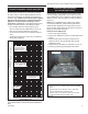
Stardance Direct Vent/Natural Vent Gas Heater 2 1 6 5 1a 4 1c 1d 3 1b 8 14 7 11 12 15 10 9 16 13 17 18 19 28a,b OT OFF • 22 23 21 D 29a,b 24 20a LE LOCAL 27 REMOTE ON • PIL 30a,b 20c 35 25 26 34 31 20b 33 37 36 38 42 41 39 T EN 40 M CE 51 50 CFM Corporation reserves the right to make changes in design, materials, specifications, prices and discontinue colors and products at any time, without notice.
Stardance Direct Vent/Natural Vent Gas Heater Stardance Direct Vent/Natural Vent Gas Heater SDDVT Series: SDDVTCB, SDDVTEB, SDDVTMB, SDDVTBS, SDDVTCH, SDDVTVG, SDDVTBD, SDDVTC Series: SDDVTCCB, SDDVTCEB, SDDVTCMB, SDDVTCBS, SDDVTCCH, SDDVTCVG, SDDVTCBD Ref. 1. 1a. 1b. 1c. 1d. 2. 3. 4. 5. 6. 7. 8. 9. 10. 11. 12. 13. 14. 15. 16. 17. 18. 19. 20a. 21. 22.
Stardance Direct Vent/Natural Vent Gas Heater Stardance Direct Vent/Natural Vent Gas Heater SDDVT Series: SDDVTCB, SDDVTEB, SDDVTMB, SDDVTBS, SDDVTCH, SDDVTVG, SDDVTBD, SDDVTC Series: SDDVTCCB, SDDVTCEB, SDDVTCMB, SDDVTCBS, SDDVTCCH, SDDVTCVG, SDDVTCBD Ref. Description 31. 32. 33. 34. 35. 36. 37. 38. 39. 40. 41. 42. 43. 44. 45. 46. 47. 48. 49. 50. 51.
Stardance Direct Vent/Natural Vent Gas Heater Optional Accessories Fan Kits FK26 Fan The FK26 fan helps distribute heated air from within the firebox out into the room. The fan is controlled by a snapstat that turns power on and off as the firebox temperature rises above and falls below a preset temperature. A rheostat provides for variable fan speeds. Specifications Screen Kit An optional screen, S30SK, for use with the operable doors is available to allow the doors to be left in the open position.
Stardance Direct Vent/Natural Vent Gas Heater 48 20012734
Stardance Direct Vent/Natural Vent Gas Heater 20012734 49
Stardance Direct Vent/Natural Vent Gas Heater 50 20012734
Direct Vent/Natural Vent Gas Heater LIMITED LIFETIMEStardance WARRANTY PRODUCT COVERED BY THIS WARRANTY All Vermont Castings brand gas stoves, gas inserts, and gas fireplaces installed in the United States of America or Canada.
CFM Corporation 2695 Meadowvale Blvd. • Mississauga, Ontario, Canada L5N 8A3 800-668-5323 • www.cfmcorp.