
User's Manual


29
Stardance Direct Vent/Natural Vent Gas Heater
20012734
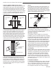
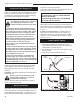
Thermostat Connection (optional)
Use only a thermostat rated for 500 millivolts.
Check the table below for the appropriate gauge ther-
mostat wire to use for the length of lead required in your
installation.
Thermostat
Wire / Gauge Maximum Run
18 20 feet
16 20 - 40 feet
14 up to 60 feet
1. Install the wall thermostat in the desired location and
run the wires to the stove location. Terminate these
leads with 1/4” female connectors.
2. Connect the thermostat wires to the valve. (Fig. 51)
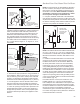
Install the Front Plate
Hold the front plate by the window bars and lift it into
position, engaging the two steel tabs on the top corners
behind the adjacent bosses in the side plates. (Fig. 52)
Then seat the Front against the sides so the tabs at the
bottom lip engage with the notches in the stove legs.
When properly installed, the bottom of the Front Plate
cannot be pulled away from the sides without also lifting
it.
ST474
Stardance
Front
10/3/00
Engage steel tabs
gehind the cast
iron bosses
Control Door
Bottom tabs engage
notch in the leg.
ST474
Fig. 52 Install the front plate.
This completes assembly of the Stardance stove.
Operation
�
The Stardance is operated with the front plate in place
with the doors open or closed. To open the front doors,
pull forward to separate the magnetic catch.
CAUTION: DO NOT TOUCH DOORS WHEN
HOT!
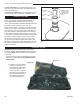
Your First Fire
Read these instructions carefully and familiarize your-
self with the burner controls. Locate the pilot assembly,
Figure 53. Follow the lighting instructions on Page 31
exactly.
During the first fire, it is not unusual to smell some odor
associated with new logs, paint and metal being heated.
Odors should dissipate within an hour or so, however,
you can open a window to provide fresh air to alleviate
the condition.
Pilot and Burner Inspection
Each time you light your heater check that the pilot
flame and burner flame patterns are as shown in Figure
55. If flame patterns are incorrect, turn the heater off.
Contact your dealer or a qualified gas technician for as-
sistance. Do not operate the heater until the pilot flame
is correct.
Follow regular maintenance procedures as described
on Page 41.
ST935
SDDVT
pilot location
6/07
ST935
Fig. 53 Pilot assembly location.