
- Vermont Castings Natural Vent Gas HeaterHome owner's Installation and Operating Manual SNV30: 3980-3996


9
Stardance Natural Vent Gas Heater
20007067
ST194
attach fan to shroud
11/99
Outer
Shroud
Slot
Inner Shroud
Slot
ST194
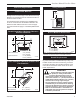
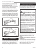
Fig. 10 Position the fan to engage the inner shroud with the
fan bracket slots and secure with sheet metal screws.
ST347a
JUV
FK28
rheostat install
9/21/00
Retaining Nut
Control Knob
ST347a
Fig. 12 Attach rheostat to left side of valve.
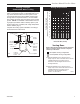
MOTOR
SNAPSTAT
ON/OFF
RHEOSTAT
WHT
WHT
BLK
BLK
BLK
GRN
BLK
POWER
ST196
FK26 fan diangram
11/99
ST196
Fig. 13 #2767 / FK26 fan wiring diagram.
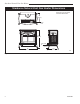
Venting System Assembly
Adjust the leg levelers as needed. They should not
extend any further from the leg than necessary.
The venting collar is on the sheet metal draft hood/heat
exchanger assembly, over the firebox. Use a B-vent
adapter, from the same maker as the rest of the B-vent
components, to join the first section of venting to the
draft hood.
The SNV30 stove includes a spill switch. Operating this
stove when not connected to a properly installed and
maintained venting system, or tampering with or discon-
necting the spill switch, can result in carbon monoxide
(CO) poisoning and possible death.
The stove includes a bracket for installing decorative 6”
(152mm) round stove pipe around the B-vent, for ap-
pearance purposes only. The decorative pipe need not
be concentric with the vent pipe.
If the installation includes decorative stove pipe around
the venting system, make a cardboard template of the
decorative pipe by tracing its circumference. Put this
template in the flue recess in the stove top. Position the
template to fit well against the front of the recess. (Fig.
14) Use this template to locate the bracket to hold the
decorative pipe. Depending on spacing, the bracket
may fit inside the decorative pipe without interfering
with the vent system. Fasten the bracket to the draft
hood/heat exchanger assembly with a sheet metal
screw.
ST372
attach
decorator pipe
bracket
5/19/00 djt
Template
Sheet Metal Screw
Bracket
ST372
Fig. 14 Use a template to locate the bracket for decorative
pipe to surround the B-vent pipe.
ST671
attach snapstat
Snapstat
Left Air Duct
ST671
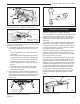
Fig. 11 Install the snapstat and connect the extension wire
terminals. View is with top removed, however, access is avail-
able through the grille opening.
NOTE: Shown without
top for clarity.
8. The rheostat control switch attaches to the left side
of the valve bracket at the front of the stove. (Fig.
12)
• Remove retaining nut from shaft of rheostat. (if
preinstalled)
• Insert the rheostat through the hole in the back
of the left side of the valve bracket, aligning the
locator pin with the smaller hole in that bracket.
• Thread the retaining nut onto the shaft of the
rheostat, tightening with a wrench. Do not over-
tighten.
• Attach the control knob to the rheostat shaft.
• Use the wire tie to secure the fan and rheostat
wire harnesses together.
9. Plug the power cord into a standard grounded 110
volt household outlet. If the fan control knob is not
turned to the OFF position, the fan will turn on when
the temperature at the snapstat reaches approxi-
mately 109°F.