
Operating instructions


XDV Direct Vent Gas Fireplace
10
10009383
The fireplace, when installed, must be
electrically connected and grounded in
accordance with local codes or, in the ab-
sence of local codes, with the current CSA
C22.1 Canadian Electrical Code.
For USA installations follow local codes
and the national electrical code ANSI/
NFPA No. 70.
It is strongly suggested that the wiring of
the EB-1 Electrical Junction Box be carried
out by a licensed electrician.
Ensure that the power to the supply line
has been disconnected before commenc-
ing this procedure.
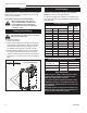
The EB-1 Electrical junction box has been fitted
standard on this model to allow for the easy connection
of an optional fan kit.
To connect the EB-1 box to the house electrical supply
follow the steps below.
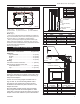
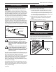
1. Unscrew the retaining screw from the EB-1 base
plate and remove the EB-1 assembly from the
appliance. (Fig. 9)
2. Remove the front cover of the EB-1 box.
3. Remove the plug socket assembly from the EB-1
box.
4. Feed the supply line in through the EB-1 opening in
the side of the appliance and then through the back
of the EB-1 assembly. (Fig. 9)
EB-1 Electrical Box
FP580
INSTA VENT FREE
EB1 JUNCTION BOX
11/18/97
OUTSIDE
Electrical Box
FRONT OF UNIT
INSIDE
FRONT OF UNIT
FP580
Fig. 9 EB-1 receptacle.
5. Connect the black wire of the power supply line to
the brass screw (polarized) of the socket assembly.
6. Connect the white wire of the power line to the
chrome screw of the socket assembly.
7. Connect the ground wire of the supply line to the
green screw of the socket assembly.
8. Refit the socket assembly back into the electrical box
and replace the cover plate. Secure the cable with
the clamp on the outside of the EB-1 base plate and
refit the EB-1 assembly to the unit with the screw
removed in step 1.