Top Vent Direct Vent Models DBT33 DBT36 DBT39 INSTALLATION INSTRUCTIONS & HOMEOWNER'S MANUAL WARNING! IF THE INFORMATION IN THIS MANUAL IS NOT FOLLOWED EXACTLY, A FIRE OR EXPLOSION MAY RESULT CAUSING PROPERTY DAMAGE, PERSONAL INJURY OR LOSS OF LIFE. FOR YOUR SAFETY WHAT TO DO IF YOU SMELL GAS: Do not try to light any appliance. Do not touch any electric switch Do not use any phone in your building. Immediately call your gas supplier from your neighbours phone. Follow the gas suppliers instructions.
TABLE OF CONTENTS Please Read The Installation & Operating Instructions Carefully Before Using The Appliance. Important: Read all the instructions and warnings carefully before starting the installation. Failure to follow these instructions fully may result in a possible re hazard and will void the manufacturers warranty. Appliance Installation instructions Important curing/burning instructions ........................................................................................
INSTALLATION & OPERATING INSTRUCTIONS This gas replace should be installed by a qualied installer in accordance with local building codes and with current CAN /CGA-B149 (. 1 or .2) Installation codes for Gas Burning Fireplaces and Equipment. FOR U.S.A Installations follow local codes and/or the current National Fuel Gas Code. ANSI Z223.1. FOR SAFE INSTALLATION AND OPERATION PLEASE NOTE THE FOLLOWING: 1.
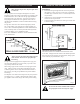
APPLIANCE DIMENSIONS Appliance Dimensions Ref. DBT33 DBT36 DBT39 A 838 mm (33") 914 mm (36") 991 mm (39") B 733 mm (28.87") 870 mm (34.25") 870 mm (34.25") C 416 mm (16.37") 533 mm (21") 533 mm (21") D 787 mm (31") 838 mm (33") 914 mm (36") E 559 mm (22") 610 mm (24") 610 mm (24") F 356 mm (14") 406 mm (16") 406 mm (16") G 810 mm (31.89") 946 mm (37.25") 946 mm (37.25") H 152 mm (6") 181 mm (7.13") 190 mm (7.5") I 149 mm (5.87") 171 mm (6.75") 159 mm (6.
CLEARANCE TO COMBUSTIBLES Appliance Top............................. 0 mm (0") Bottom....................... 0 mm (0") Side............................ 0 mm (0") Back........................... 0 mm (0") Venting Concentric sections of DV Vent Top, bottom & sides .. 25 mm (1") MANTELS The height that a combustible mantel is tted above the replace is dependent on the depth of the mantel. This also applies to the distance between the mantel leg (if tted) and the replace.
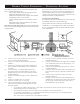
DBT33 / DBT36 / DBT39 CERTIFIED TO ANSI Z21.88b-1999 / CSA Z2.33b-M99 Vented Gas Fireplace Heaters GAS SPECIFICATIONS Fig. 3 Model Fuel Gas Control Max. Min. Input Input BTU/h BTU/h DBT33RN Nat. Millivolt 15,000 10,500 DBT33RP Prop. Millivolt 15,000 11,250 DBT36RN Nat. Millivolt 18,000 12,600 DBT36RP Prop. Millivolt 18,000 13,500 DBT39RN Nat. Millivolt 22,000 15,400 DBT39RP Prop. Millivolt 22,000 16,500 Fig.
GAS LINE INSTALLATION REMOTE ON/OFF SWITCH Installation When purging the gas lines, the front glass must be removed. 1. The gas pipeline can be brought in through the rear of the replace as well as the bottom. Knockouts are provided on the bottom behind the valve to allow for the gas pipe installation and testing of any gas connection. It is most convenient to bring the gas line in from the rear right side of the valve as this allows fan installation or removal without disconnecting the gas line.
CONVERTING THE APPLIANCE FROM LP TO NATURAL GAS OR NATURAL GAS TO LP. a) Using a suitable small screwdriver lift out the central regulator cap from the ‘Hi - Lo’ knob on the valve. b) Unscrew the exposed conversion screw. c) Insert the new colour coded conversion screw. Do not over-tighten the screw, it must be nger tight. d) Ret the regulator cap. e) Mount the conversion label supplied with the conversion screw to the valve in a visible position. 10.
GENERAL VENTING INFORMATION — TERMINATION LOCATION Your replace is approved to be vented either through the side wall, or vertically through the roof. – Only venting components specically approved and labelled for this replace may be used. – Minimum clearances between vent pipes and combustible materials is one (1") inch (25 mm). – Venting terminals shall not be recessed into a wall or siding. – Horizontal venting must be installed on a level plane without any incline or decline.
Fig. 11 Fig. 12 Fig. 13 DBT33/DBT36/DBT39 Fig. 14 -10- Fig.
HOW TO USE THE VENT GRAPH GENERAL INFORMATION ON ASSEMBLING DV COMPONENTS The vent chart should be read in conjunction with the following vent installation instructions to determin the relationship of the vertical and horizontal dimensions of the vent system 1. Determine the height of the centre of the horizontal vent pipe exiting through the outer wall. Using this dimension on the Sidewall Vent Graph below, locate the point it intersects with the slanted graph line. 2.
VERTICAL SIDEWALL APPLICATIONS • Since it is very important that the venting system maintain its balance between the combustion air intake and the ue gas exhaust, certain limitations as to vent congurations apply and must be strictly adhered to. The Vent Graph showing the relationship between vertical and horizontal side wall venting will help to determine the various dimensions allowable.
VERTICAL SIDEWALL INSTALLATIONS STEP 1 Locate vent opening on the wall. It may be necessary to rst position the replace and measure to obtain hole location. Depending on whether the wall is combustible or non-combustible, cut opening to size. (Fig. 22) (For combustible walls rst frame in opening. Fig. 22). Fig. 24 STEP 4 Apply a bead of silicone to the inner and outer ue collars of the replace and using three (3) screws attach an appropriate length of vent to the replace.
STEP 6 Use appropriate length of pipe sections - telescopic or xed and install the horizontal vent sections. The sections which go through the wall are packaged with the starter kit, and can be cut to suit if necessary. (Fig. 26). Sealing vent pipe and restop gaps with high temperature sealant will restrict cold air being drawn in around replace. Fig. 27 Support horizontal pipes every 3' (91 cm) with metal pipe straps. Check replace to make sure it is levelled and properly positioned.
VERTICAL THROUGH-THE-ROOF APPLICATIONS. DO NOT BACK FILL AROUND SNORKEL. A CLEARANCE OF AT LEAST 4” MUST BE MAINTAINED BETWEEN THE SNORKEL AND THE SOIL This Gas Fireplace has been approved for, • Vertical installations up to 40' (12 m) in height. Up to a 10' horizontal vent run can be installed within the vent system using a maximum of two 90º elbows. (Fig. 30) Fig. 28 If the foundation is recessed, use recess brackets (not supplied) for securing lower portion of the snorkel.
Fig. 32 4. Remove the two (2) screws from the top face of the bafe assembly, Fig. 32. Place the restrictor plate as shown in Fig. 34 and secure by retting the screws. Fig. 33 Fig. 31 • • 7DVCS must be used to support offsets. (Fig. 36)This application will require that you rst determine the roof pitch and use the appropriate starter kit. (See Venting Components List) The minimum height of the vent above the highest point of penetration through the roof is 2'. See Fig. 38. Fig.
VERTICAL THROUGH-THE-ROOF INSTALLATION 1. 2. 3. 4. 5. 6. 9. Install storm collar and seal around the pipe. 10. Add additional vent lengths for proper height. Fig. 38. 11. Apply high temperature sealant to 4" and 7" collars of vertical vent termination and install. Locate your replace. Plumb to centre of the (4") ue collar from ceiling above and mark position. Cut opening equal to 9-3/8" x 9-3/8" (240 mm x 240 mm). Proceed to plumb for additional openings through the roof.
CRIMPED END VENTING COMPONENTS Starter Kit -Model 7DVSK - Sidewall Venting Starter Kit - Model 7TDVSKV - Vertical Venting for 7TDVSKV-A order 1/12 to 6/12 roof pitch for 7TDVSKV-B order 7/12 to 12/12 roof pitch for 7TDVSKV-F order at roof Starter Kit - Model 7DVSKS -Snorkel Kit for Below Grade Installation 45º elbow kit 7DVT45 for Vertical Installation Offsets 90º transition elbow kit 7DVRT90 for Vertical Sidewall Applications or thru-the-roof.
TWIST LOCK VENTING COMPONENTS Starter Kit -Model 7TDVSK - Sidewall Venting Starter Kit - Model 7TDVSKV - Vertical Venting for 7TDVSKV-A order 1/12 to 6/12 roof pitch for 7TDVSKV-B order 7/12 to 12/12 roof pitch for 7TDVSKV-F order at roof Starter Kit - Model 7TDVSKS -Snorkel Kit for Below Grade Installation 45º elbow kit 7TDV45 for Vertical Installation Offsets 90º transition elbow kit 7TDV90 for Vertical Sidewall Applications or thru-the-roof.
GENERAL OPERATING INSTRUCTIONS GLASS INFORMATION GLASS / FRAME REMOVAL 1. 2. Only glass approved by CFM Majestic Inc. should be used on this replace. • • • • 3. 4. 5. The use of any non-approved replacement glass will void all product warranties. Care must be taken to avoid breakage of the glass. Under no circumstances should this appliance be operated without the front glass in place, or with the glass in a damaged condition.
INSTALLATION OF LOGS & LAVA ROCK Refer to the log identication chart to identify specic log numbers. 1. Remove the front glass / frame assembly. 2. Remove the logs from their packaging. The logs are fragile and should be handled with care. Keep the packaging material out of the reach of children and dispose of the material in a safe manner 3. 4 5. 6. 7. 8. 9. DBT33 Fig. 41 Place the rear log (see chart for identication number) in the rear support channel.
FLAME & TEMPERATURE ADJUSTMENT RN/RP & EN/EP Models For units equipped with ‘HI/LO’ valves the ame adjustment is accomplished by rotating the ‘HI/LO’ adjustment knob located near the centre of the gas control valve, Fig. 44 & 45 DBT33 Fig. 47 Fig. 44 Fig. 45 DBT36 Fig. 48 FLAME CHARACTERISTICS It is important to periodically perform a visual check of the pilot and burner ames. Compare them to the pictorials illustrated below, Figs. 43 - 49.
LIGHTING AND OPERATING INSTRUCTIONS FOR YOUR SAFETY READ BEFORE LIGHTING WARNING: If you do not follow these instructions exactly, a re or explosion may result causing property damage, personal injury or loss of life. A. This replace has a pilot which must be lit manually. When lighting the pilot follow these instructions exactly. B. BEFORE LIGHTING smell all around the replace area for gas. Be sure to smell next to the oor because some gas is heavier than air and will settle on the oor.
TROUBLE SHOOTING THE GAS CONTROL SYSTEM HONEYWELL MILLIVOLT VALVE DBT33/DBT36/DBT39 -24- 10002789/0
TROUBLE SHOOTING THE GAS CONTROL SYSTEM SIT NOVA 820 MILLIVOLT VALVE Note: Before trouble shooting the gas control system, be sure external gas shut off is in the "On" position. WARNING: BEFORE DOING ANY GAS CONTROL SERVICE WORK, REMOVE GLASS FRONT. SYMPTOM 1. Spark ignitor will not light POSSIBLE CAUSES A. Defective or misaligned electrode at pilot. Using a match, light pilot. If pilot lights, turn off pilot and push the red button again.
REPLACEMENT PARTS LIST Items marked ‘*’ are not shown in the following parts pictorial page. Ref. Description DBT33 DBT36 DBT39 10000470 10000023 10000024 1 Log Set (complete) 1a Log - Front left BA2 BB6 BC5 1b Log - Front right BA3 BB7 BC6 1c Log - rear BA4 BB8 BC7 1d Log - Top left BA5 BB9 BC8 1e Log - Top right BA6 BB10 BC9 * Lava rock package 10001454 10001454 10001454 * Ember material 51915 51915 51915 2a Burner housing with tiles, Nat.
Ref.
PARTS PICTORIAL DBT33/DBT36/DBT39 -28- 10002789/0
OPTIONAL ACCESSORIES AVAILABLE EB-1 ELECTRICAL BOX The EB-1 Electrical junction box when tted and correctly wired gives an easy and convenient power outlet for the optioal fan kit. If the EB-1 electrical junction box is being tted the replace must be electrically connected and grounded in accordance with local codes or, in the absence of local codes, with the current CSA C22.1 Canadian Electric Code. For U.S.A. installations follow the local codes and the national electrical code ANSI/NFPA No 70.
3 4 WIRING INSTRUCTIONS Locate the fan speed control unit. This can be tted behind the lower louvre assembly as in Fig. 50 or located remotely in a conveniently located wall mounted electrical box. Remote location of the speed control will require suitable extension of the component wiring. The power supply may be connected in 2 ways: Method A Route the 6' lead tted to the unit to a conveniently located wall socket. Method B The EB1 receptacle box (Pt. # ZA1200) may be hard wired into the house supply.
CERAMIC REFRACTORY KITS Ceramic refractory panels are available in kit form for the DBT series appliances. Appliance Model Kit Name DBT33 33BDVTCR DBT36 36BDVCR DBT39 39BDVCR Take care when handling the refractory panels as they are fragile until held in place and supported. Fig. 53 Installation, refer to Figs. 52 & 53 1. 2. 3. 4. 5. 6. 7. 8. FRONT WINDOW SCREEN Remove the front frame/glass assembly. Remove the logs. Place the lower supports for the side refractory panels on the base of the rebox.
DECORATIVE BAY WINDOWS Bay window kits are available for the DBT33, DBT36 & DBT39 model appliances. When tting the Bay Window Kits the original front frame/glass assembly MUST remain in place. The Bay Window kit is tted over the existing front glass. Installation 1. 2. 3. 4. 5. 6. 7. Remove the upper and lower brass window trims. Remove the existing bottom louvre assembly complete with the hinges.
10002789/0 -33- DBT33/DBT36/DBT39
LIMITED WARRANTY & EXTENDED LIFE TIME PROTECTION For Gas Appliance Products* BASIC WARRANTY: The CFM Majestic, Inc.™ (hereinafter referred to collectively as the "Company") warrants that your new Vermont Castings Gas Appliance is free from manufacturing and material defects for a period of one year from date of installation, subject to the following conditions and limitations. GARANTIE DE BASE: The CFM Majestic. Inc.