
Operating instructions


DBT33/DBT36/DBT39 -8- 10002789/0
CONVERTING THE APPLIANCE
FROM LP TO NATURAL GAS OR
NATURAL GAS TO LP.
The DBT33 is convertible between Natural Gas an LP gas
(and vice-versa) with the use of a conversion kit purchased
seperately, see your dealer for the correct part number.
The DBT36 & 39 can only be converted from
Propane to Natural gas.
The conversion of this appliance from one gas
to another must be carried out by an authorized
service provider.
1. Disconnect power to the unit and shut off the gas supply.
2. Remove the glass/frame assembly.
3. Carefully remove the logs & lava rock material
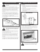
4. Remove the screws that are holding the burner housing
in place.
5. Remove the burner housing. Depending on the model of
the appliance you may have to loosen the pilot bracket
retaining screw/nut to allow the pilot and bracket assem-
bly to tilt and give enough clearance to remove the burner
housing.
6. Remove the main burner orice and replace it with the
orice supplied in the conversion kit.
7. SIT Top Convertible Pilot
Gently lift off the pilot hood from the pilot. (Do not
remove the spring clip holding the hood in place). Using
a correctly sized Allen key unscrew the exposed orice.
Insert the new orice supplied in the kit, do not over
tighten the orice. Replace the pilot hood ensuring the
index tab aligns with the notch on the hood.
PSE Pilot
Using a suitable wrench on the hexagonal body unscrew
the pilot hood assembly from the pilot, do not twist the
hood itself. Remove the orice and replace it with the
new orice supplied in the kit. Ret the pilot hood
assembly. Do not over-tighten the pilot hood. The hood
must return to its original alignment. Take care not to
damage the thermocouple, thermopile or igniter.
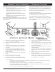
9. SIT 820 NOVA Gas Control Valve (Fig. 9)
a) Using a Torx T20 or slotted screwdriver, remove and
save the three pressure regulator mounting screws (A),
pressure regulator tower (B) and diaphragm (C).
b) Ensure the rubber gasket (D) is properly positioned and
install the new Hi/Lo pressure regulator to the valve using
the new screws (E) supplied with the kit. Tighten screws
securely. (Reference torque - 25 in.Lb).
c) Install the enclosed identication label (F) to the valve
body where it can be easily seen.
Honeywell Gas Control Valve (Fig. 10)
The Honeywell valve tted to this unit is suitable
for use with LP or Natural Gas. It is converted to
the required gas application by the installation of a
colour coded “conversion screw”.
a) Using a suitable small screwdriver lift out the central
regulator cap from the ‘Hi - Lo’ knob on the valve.
b) Unscrew the exposed conversion screw.
c) Insert the new colour coded conversion screw. Do not
over-tighten the screw, it must be nger tight.
d) Ret the regulator cap.
e) Mount the conversion label supplied with the conver-
sion screw to the valve in a visible position.
10. Reassemble the replace in the reverse order, except for
the front glass. Leave this off until the unit has been
checked for leaks and the gas supply line has been bled.
11. After bleeding the gas line and checking for leaks with a
soap solution, replace the front glass. Fire up the unit,
check for ame impingement on the logs, adjusting them
if necessary. Check the manifold and supply pressures
against the appliance specications.
The procedure for converting from one gas to
another is the same regardless of the initial gas
used. The only variation is in the orice sizes
and component part numbers. Your authorized
service provider will ensure the correct parts are
used.
Fig. 9
Fig. 10