
Operating instructions


20
Vermont Castings, Majestic Products DVRT36/ 39/ 43
10002428
• Up to two (2) 45° elbows may be used within the
horizontal run. For each 45° elbow used on the
horizontal plane, the maximum horizontal length
must be reduced by 18” (450mm).
Example: Maximum horizontal length
No elbows = 10’ (3m)
1 x 45° elbows = 8.5’ (2.6m)
2 x 45° elbows = 7’ (2.1m)
•A minimum of an 8’ (2.5m) vertical rise is required.
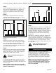
• Two (2) sets of 45° elbows offsets may be used
within the vertical sections. From 0 to a maximum of
8’ (2.5m) of vent pipe can be used between elbows.
(Fig. 34)
• 7DVCS supports offsets. (Fig. 34) This application
requires you to first determine the roof pitch and
use the appropriate starter kit. See Venting
Components List.
• The maximum angular variation allowed in the
system is 270°. (Fig. 34)
• Minimum height of the vent above the highest point
of penetration through the roof is 2’ (610mm). (Fig.
37) See Note 2 on Page 12.
1. Locate your fireplace.
2. Plumb to center of the 4” flue collar from ceiling
above and mark position.
3. Cut opening equal to 9¹⁄₂”x 9¹⁄₂” (240 x 240mm).
4. Proceed to plumb for additional openings through
the roof. In all cases, the opening must provide a
minimum of 1” (25mm) clearance to the vent pipe;
i.e., the hole must be at least 9¹⁄₂”x 9¹⁄₂” (240 x
240mm).
5. Place fireplace into position.
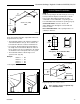
6. Place firestop(s) #7DVFS or Attic Insulation Shield
#7DVAIS into position and secure. (Fig. 35)
Vertical Through-the-Roof Installation
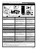
7. Install roof support and roof flashing, making sure
the upper flange is below the shingles. (Fig. 36)
8. Install appropriate pipe sections until the venting is
above the flashing. (Fig. 38)
9. Install storm collar and seal around the pipe.
10. Add additional vent lengths for proper height.
(Fig. 37)
11. Apply high temperature sealant to 4” and 7” collars
of vertical vent termination and install.
If there is a room above ceiling level, fire
stop spacer must be installed on both
the bottom and the top side of the
ceiling joists. If an attic is above ceiling
level a 7DVAIS (Attic Insulation Shield)
must be installed.
The enlarged ends of the vent section
always face downward.
Typical Roof
Support
Application
Typical Ceiling
Support
Application
FP1184
Fig. 36 Venting supports.
1
2
3
4
1 + 2 + 3 + 4 = 270°
FP1179
Fig. 34 Maximum elbow usage.
1
2
3
4
Attic
Insulation Shield
Upper Floor
Ceiling
Installation
Joist
Nails (4)
Firestop
Spacer
FP1029
Fig. 35 Attic insulation shield and firestop spacer.
11"
(279mm)
11"
(279mm)