INSTALLER / CONSUMER SAFETY INFORMATION PLEASE READ THIS MANUAL BEFORE INSTALLING AND USING APPLIANCE. WARNING! IF THE INFORMATION IN THIS MANUAL IS NOT FOLLOWED EXACTLY, A FIRE OR EXPLOSION MAY RESULT CAUSING PROPERTY DAMAGE, PERSONAL INJURY OR LOSS OF LIFE. FOR YOUR SAFETY Installation and service must be performed by a qualified installer, service agency or the gas suppler.
Radiance Direct Vent Gas Heater Table of Contents PLEASE READ THE INSTALLATION & OPERATING INSTRUCTIONS BEFORE USING APPLIANCE. Thank you and congratulations on your purchase of a Vermont Castings stove. IMPORTANT: Read all instructions and warnings carefully before starting installation. Failure to follow these instructions may result in a possible fire hazard and will void the warranty. Installation & General Information .....................................................................................
Radiance Direct Vent Gas Heater Installation & Operating Instructions The Radiance Direct Vent Room Heater, Model Nos. RADVTCB, RADVTEB, RADVTMB, RADVTBS, RADVTCH, RADVTVG, RADVTBD, RADVTBB, RADVTCG, RADVTGG, RADVTSG, RADVTCCB, RADVTCEB, RADVTCMB, RADVTCBS, RADVTCCH, RADVTCVG, RADVTCBD, RADVTCBB, RADVTCCG, RADVTCSG, is a vented gas appliance listed to the ANSI standard Z21.88-2005 and CSA-2.33-2005 for Vented Room Heaters, and CSA 2.17-M91, Gas-Fired Appliances For Use at High Altitudes.
Radiance Direct Vent Gas Heater Installation & Operating Instructions Requirements for the Commonwealth of Massachusetts All gas fitting and installation of this heater shall only be done by a licensed gas fitter or licensed plumber.
Radiance Direct Vent Gas Heater Radiance Direct Vent Stove Dimensions See Page 7 for Flue Collar Centerline Dimensions. 14���" (378 mm) 7" Outer Dia. (178 mm) Supply Inlet 4���" (120 mm) Flue Collar C L 14���" (378 mm) 7" Outer Dia. (178 mm) Supply Inlet 4���" (120 mm) C L 9���" (241 mm) 8����" (218 mm) Flue Collar RADVT Models 13���” (340 mm) RADVTC Models 11” (279 mm) 29���" (758 mm) RADIANCE 28" (711 mm) Supply Inlet 5" (127 mm) 18���" (464 mm) 31" (787 mm) Fig.
Radiance Direct Vent Gas Heater Installation Requirements The installation must conform with local codes or, in the absence of local codes, with the National Fuel Gas Code, ANSI Z223.1/NFPA 54 - latest edition. (EXCEPTION: Do not derate this appliance for altitude. Maintain the manifold pressure at 3.5” w.c. for Natural Gas, and 10” w.c. for Propane). In Canada, installation must be in accordance with the current CSA B-149.1 Installation Codes and/or local codes.
Radiance Direct Vent Gas Heater Parallel Installation: Minimum Clearance and Flue Centerline Wall Centerline from Floor Direct Vent Only 42" (1070mm) Min. Alcove Width 4" (102mm) 48" (1220mm) Max. Alcove Depth ST130 A 6" (150mm) 6" (150mm) Fig. 3 Parallel installation, minimum back and side clearances, and flue centerlines.
Radiance Direct Vent Gas Heater Gas Specifications RADVT Series Nat Millivolt RADVT Series Prop Millivolt RADVTC Series Nat Comfort Control RADVTC Series Prop Comfort Control 38,000 36,000 38,000 36,000 25,000 25,000 25,000 25,000 Weight: Fully assembled; 350 lbs. Gas Inlet and Manifold Pressures Inlet Minimum Natural 5.5” w.c. LP (Propane) 11.0” w.c. Inlet Maximum 14.0” w.c. 14.0” w.c. Manifold Pressure 3.5” w.c. 10” w.c.
Radiance Direct Vent Gas Heater Restrictor Plate Adjustment for Extended Pipe Runs Vertical Termination A vertical vent system must terminate no less than 8’ (2.44 m) and no more than 40’ (12 m) above the appliance flue collar. A restrictor plate (supplied) must be used, where specified, in all vertically terminated vent systems. (Refer to Figure 8) NOTE: The restrictor plate supplied with the vertical termination should be discarded. Adjust the restrictor plate according to recommendations in Figure 10.
Radiance Direct Vent Gas Heater Vent Termination Clearances When planning the installation, consider the location of the vent terminal and clearances. Some of the most common clearances to keep in mind are shown in Figure 11. Important: All vent clearances must be maintained. Check your vent termination clearances against Figures 11 through 13. The vent should be placed so that people cannot be burned by accidentally touching the vent surfaces when the stove is operating.
Radiance Direct Vent Gas Heater General Venting Information - Termination Location INSIDE CORNER DETAIL G V H A N N D L V E C B V F B ����� ������ B V Ope Operable rable V B B B V J X X AIR SUPPLY INLET M I A CFM145a V VENT TERMINATION V Fixed Closed C = Clearance to permanently closed window D = Vertical clearance to ventilated soffit located above the terminal within a horizontal distance of 2’ (610mm) from the center line of the terminal E = Clearance to unventilated soffit
Radiance Direct Vent Gas Heater Termination Clearances Termination clearances for buildings with combustible and noncombustible exteriors. Inside Corner Alcove Applications* Outside Corner G= Combustible 6" (152 mm) G F= Combustible 6" (152 mm) Noncombustible 2" (51 mm) V Noncombustible 2" (51 mm) V C V E O F Balcony with perpendicular side wall Balcony with no side wall D C E = Min. 6” (152 mm) for non-vinyl sidewalls Min. 12” (305 mm) for vinyl sidewalls O = 8’ (2.4 m) Min.
Radiance Direct Vent Gas Heater Venting Requirements and Options Approved Vent System Components The Radiance Heater must be vented to the outdoors through an adjacent exterior wall or through the roof. The venting system must be comprised of the appropriate listed venting components specified on this page. These parts are available from DuraVent Corporation, Selkirk Corporation or your Vermont Castings Dealer. See Figure 4 for dimensions relevant to the standard minimum-vent kits.
Radiance Direct Vent Gas Heater CFM Vent Components The following kits are available to meet the needs of most installations. All pipe has a 7” outer diameter and includes a 4” diameter inner section. A (CG) designation indicates the part is finished in Charcoal Gray paint. Consult your dealer about other vent parts that may be appropriate to complete the installation. Min.
Radiance Direct Vent Gas Heater Assembly Procedures WARNING Failure to position the parts in accordance with these diagrams or failure to use only parts specifically approved for use with this heater may result in property damage or personal injury. This heater and components are heavy. Have help available for assembly. Tools Required • Phillips screwdriver (stub) • utility knife • power drill • reciprocating saw • metal drill bit: size 28 (.140”/3.5mm) • 9/16” wrench Parts Bag Contents: ST720 Fig.
Radiance Direct Vent Gas Heater WARNING This appliance is equipped with a three-prong (grounded) plug for your protection against shock hazard and should be plugged directly into a properly grounded three-prong receptacle. Do not cut or remove the grounding prong from this plug. Install the Optional Fan If you are installing the optional convection Fan Kit #2767 (FK26), continue here. It is easiest to install fan kit before connecting gas line.
Radiance Direct Vent Gas Heater Venting System Assembly General Information The Radiance is approved for installation only with the vent components listed on Pages 13 and 14. Follow the vent component instructions exactly. For U.S. installations: The venting system must conform with local codes and/or the current National Fuel Gas Code, ANSI Z223.1/NFPA 54. ENT CEM For Canadian installations: The venting system must conform to the current CSA B149.1 installation code.
Radiance Direct Vent Gas Heater Inner Adpater Pipe 1/4-20 x 3/8” Phillips Screws minimum of 1¹⁄₂” over the flue outlet. The outside of the Direct-Temp Length will fit inside the flue outlet Secure with a minimum of two #8 x 1/4” sheet metal screws and seal with hi-temp silicone. For units factory equipped with appliance adapters from other brands of Direct Vent systems, it is permissible to simply slide a length of DT pipe over the appliance adapter.
Radiance Direct Vent Gas Heater 12” (305mm) Max. Length Sleeve X #8 Sheet Metal Screws ST215 Fig. 27 Measure the horizontal length. Firestop ZCS103 Fig. 25 Assemble the wall sleeve and firestop. ZCS103 4. For CFM Vent Pipe only: If necessary, measure Clearance Sleeve to determine Zero the vertical length (X) of pipe required & Firestop from the adapter pipe to the wall cutout centerline, including a 2”12/6/99 overlapdjt at the joint. (Fig. 26) use a hacksaw or tin snips to trim the pipe as needed.
Radiance Direct Vent Gas Heater 11. For CFM only: Install Charcoal Gray Pipe Rings (#7FSDRG) or Polished Brass Pipe Rings (#7FSDRP) at pipe joints, if desired. Vent Termination Below Grade Install Snorkel Kit #7FSDVSKS when it is not possible to meet the required vent termination clearances of 12” (305 mm) above grade level. The snorkel kit will allow installation depth of down to 7” (178 mm) below grade level.
Radiance Direct Vent Gas Heater #7DVAIS Attic Insulation Shield #7DVFS Firestop in Upper Floor Use Four 8d Nails #7DVFS Firestop in Ceiling ST222 Fig. 32 Install firestops and attic insulation shield. 7. Install the appropriate roof support and flashing, ST222 making certain thatvent thethru upper ceilingflange of the flashing 12/99 base is below the shingles. (Fig. 33) 8. Install appropriate pipe sections until the vent run reaches above the flashing.
Radiance Direct Vent Gas Heater it by screwing the support plate to the top of the properly framed ceiling joist opening, using screws provided. A round trim plate (TP) is attached to the ceiling, using screws, to provide a finished appearance once installed. (Fig. 35) Gasket Outlet End Inlet End Lock Tab To Termination To Appliance Fig. 34 Joint connection. Vent Termination (VC) Storm Collar (SC) Ceiling Support Collar Ceiling Support Plate ST922 ����� ������������ ���� Trim Plate ST923 Fig.
Radiance Direct Vent Gas Heater The Cathedral Ceiling Support (CCS) may be used in pitched or flat ceiling installations and comes with a support collar and a decorative two part square trim plate. Install by inserting the support box down through the framed joist opening (end with round hole first) in the ceiling using tin snips, cut the corners of the open end of the box such that the sides can be folded down over the top of the joist framing members. Nail the folded sides to the top of the framing. (Fig.
Radiance Direct Vent Gas Heater from traffic areas such as walkways if it is less than 7’ (2.1 m) high. Refer to Pages 11, 12, Figures 11, 12 for more detail.
Radiance Direct Vent Gas Heater If the wall is brick or concrete, and contains no combustible material, a 7” (178 mm) round penetration hole is adequate. The wall thimble is not required. The perforated straps of the horizontal termination provide a method of attachment. These can either be threaded through the opening or wall thimble (if used) and screwed to the pipe or removed with a pair of tin snips if not used. Use proper masonry fasteners to attach the horizontal termination to the wall. 7.
Radiance Direct Vent Gas Heater the assembled pipe to the appliance. Determine and mark the location of where the support collar will be attached to the pipe. Disconnect and remove assembled pipe. Attach the support collar per Step 10 (where marked) and reinstall assembly. This is due to limited space within the cathedral ceiling support box. Install any required offset supports. 11.
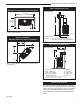
Radiance Direct Vent Gas Heater Rear Log 2. Install the rear log by placing it on the ember bed toward the back of the firebox. (Fig. 48) The log should touch the back wall of the firebox. When the log is in place, the two (2) notches on the bottom of the log rest on the two (2) ribs on the back side of the ember bed. (Fig. 49) Figure 48 LG488 Ribs for Rear Log Figure 49 Ember Bed ����� �������� ���� Rib and Flat Spot for Front Right Log Rib Flat Spot for Front Left Log 3.
Radiance Direct Vent Gas Heater Left Cross Log Rear Log Right Cross Log Figure 51 Front Right Log LG490 Front Left Log Connect the Gas Supply Line Check the Rating Plate attached by a steel cable to the firebox, to confirm that you have the appropriate firebox ����� for the type of fuel to be used. The Radiance may be converted from one gas to another using the appropri- �������� ���� ate Fuel Conversion Kit listed on Page 46. In the U.S.
Radiance Direct Vent Gas Heater PILOT ADJ THIS APPLIANCE SHOULD BE CONNECTED TO THE GAS SUPPLY ONLY BY A QUALIFIED GAS SERVICE TECHNICIAN. FOLLOW ALL LOCAL CODES. TPTH THERE MUST BE A GAS SHUT-OFF BETWEEN THE STOVE AND THE SUPPLY. TP Install ON/OFF Switch Switch Assembly Existing Holes Screws ST315 Fig. 52 Attach switch assembly to rear shroud. TH The switch assembly parts are found in the parts bag. 1.
Radiance Direct Vent Gas Heater HI Turn clockwise to lower flame height. LO Turn counterclockwise to increase flame height. Fig. 55 Flame adjustment knob for SIT valve. FP390 FLAME ADJUSTMENT KNOB Pilot Assembly Flame11/21/96 Characteristics ST476 Fig. 54 Pilot Assembly location. ST477 Follow regular maintenance procedures as described Stardance on Page 41. It is important to periodically perform a visual check of the pilot and the burner flames. Compare them to Figure 56.
Radiance Direct Vent Gas Heater Lighting and Operating Instructions FOR YOUR SAFETY READ BEFORE LIGHTING WARNING:If you do not follow these instructions exactly, a fire or explosion may result causing property damage, personal injury or loss of life. A. This heater has a pilot which must be lit manually. When lighting the pilot follow these instructions exactly. B. BEFORE LIGHTING smell all around the heater area for gas.
Radiance Direct Vent Gas Heater Troubleshooting the Gas Control System (RADVT Series) SIT NOVA 820 MILLIVOLT VALVE NOTE: Before trouble shooting the gas control system, be sure external gas shut off is in the “On” position. Symptom Possible Causes Corrective Action 1. Spark ignitor will not light A. Defective or misaligned electrode at pilot Using a match, light pilot. If pilot lights, turn off pilot and push the red button again.
Radiance Direct Vent Gas Heater Instructions for Comfort Control Valve RADVTC Series The Comfort Control valve allows remote control of temperature, fan and flame appearance. NOTE: The antenna should hang in free air away from grounded metal. Operation 1. If the manual switch is in remote position, switch it to LOCAL. (Fig. 57) 2. Turn the pilotstat knob counterclockwise from OFF to the PILOT position, push the knob down, and hold in position. The pilot valve opens and allows gas to flow to the pilot burner.
Radiance Direct Vent Gas Heater Auto Mode Pilot Assembly In the AUTO mode, the room temperature, set temperature, flame and fan levels will be shown. AUTO will appear next to both the flame and fan icons. Blower When the control is in the AUTO mode, the main burner will turn on/off or modulate based on the heat needed to maintain the set temperature. The flame level will change automatically to optimize the heat output needed to maintain the set temperature.
Radiance Direct Vent Gas Heater Comfort Control Valve System Sequence of Operation with Transmitter Set manual switch to local or remote Five minute wait period Light pilot burner Did the LED stop blinking? No Review LED failure analysis. Release pilotstat knob. Yes Turn pilotstat knob from PILOT to ON. Cycle switch once and leave in remote. Press any key on transmitter for recognition operation.
Radiance Direct Vent Gas Heater Auto Path If the manual switch is set to REMOTE, press the mode button to display AUTO on the transmitter. Does the transmitter display the room and temperture setting? Move switch from LOCAL to REMOTE. Press any key within 30 seconds.
Radiance Direct Vent Gas Heater Fuel Conversion Instructions Gas Supply Inlet ST226a Fig. 60 Attach the gas line to the right side of the valve. Conversion Precautions ST226 Before proceeding, turn control knob on valve to OFF attach gas line and turn gas supply OFF. TurndjtOFF any electricity that 12/8/99 may be going to the appliance. Conversion Procedure 1. Remove stove front. Lift stove front up and then swing bottom out and away to disengage from the stove body. (Page 26, Fig. 46) 2.
Radiance Direct Vent Gas Heater 2. Remove and replace plug on lower right hand side of the valve; Red for LP and Blue for NG. (Page 32, Fig. 57) 3. Remove motor top cap using a standard slotted screwdriver. Depress and turn center plunger until arrow points to correct screw. Red for LP and Blue for NG. NOTE: Plunger will “snap” into NG position when arrow is close to blue screw. It will not “snap” at LP (Red) position. (Fig. 66) Pilot Hood Pilot Bracket CO105a Fig. 68 Remove pilot hood.
Radiance Direct Vent Gas Heater 3. Remove injector orifice from left burner bracket with a 1/2” wrench. Use a back up wrench to prevent damage to the manifold. (Fig. 74) Pilot Orifice CO1044 Fig. 71 Remove pilot orifice. Burner Orifice Conversion 1. Remove three (3) 3/8” nuts on bottom side of burner pan. (Fig. 72) 2. Carefully remove ember bed by tilting the right side CO144 up and lifting out toward the right side of the unit. RF Pilot conversion (Fig. 73) 6/07Remove djt Nut CO145 Fig.
Radiance Direct Vent Gas Heater 5. Replace glass and stove front. 6. Restore gas to system and relight appliance according to Lighting Instructions on Page 31. 7. Leak check the system using a gas leak detector solution. 8. Relight the main burner in both the “HI” and “LO” positions to verify proper burner ignition and operation. Conversion is complete. Table 2. Injector Orifice Size Matrix Conversion to LP Model RADVT RADVTC Kit # 20012729 Orifice Part # 1.
Radiance Direct Vent Gas Heater Maintenance Your Radiance Gas Heater will provide years of service with minimal upkeep. The following procedures will help ensure that your stove continues to function properly. Annual System Inspection Have the entire heater and venting system inspected annually by a qualified gas technician. Replace any worn or broken parts. Cleaning the Glass WARNING: Allow the glass to cool completely before attempting to clean.
Radiance Direct Vent Gas Heater ST179 Fig. 78 Wrap the gasket material around the outside edge of the glass. ST141 Fig. 77 Release the latches to remove the glass frame. Gasket Replacement ST141 The Radiance Gas Heater uses a ‘tadpole’ type gasket pull glass latch 10/99 and the frame. In time, to seal between the glass panel this gasket can become brittle and compressed and should be replaced. New gasket is available from your dealer. Shut off the gas supply and allow the stove to cool.
Radiance Direct Vent Gas Heater Wiring Diagrams OFF ON Thermopile Black On/Off Switch Wiring TP/TH BL Millivolt Gas Valve TP Black TH FAN POWER CORD Chassis Ground St124b on/off/switch wiring 1/11/00 djt TP TH K BLK FAN JUNCTION BOX Thermopile Black TP/TH BL Thermostat (Optional) Optional Thermostat Wiring K GRN ST124b Thermostat (Optional) BLK WHT Strain Relief ON / OFF Rheostat Millivolt Gas Valve Black Snapstat ST124c Fig. 80 On/off switch and optional thermostat circuit.
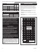
Radiance Direct Vent Gas Heater 1 5 1a 7 1b 8 4 1c 6 3 1e 1d 10 11 9 22 21 2 20 14 19 15 24 16 23 12 7 17 18 27a 29 30 28 31 34 27b 25 27c 32 13 33 26a,b 36a,b 35a,b 37a,b,c 40 38 41 42 T 47 OFF • 44 51 48 46 LE D REMOTE LOCAL ON • PILO 50 45 43 52 CFM Corporation reserves the right to make changes in design, materials, specifications, prices and discontinue colors and products at any time, 12697 without notice.
Radiance Direct Vent Gas Heater Radiance Direct Vent Gas Heater (continued) Models: RADVT Series: RADVTCB, RADVTEB, RADVTMB, RADVTBS, RADVTCH, RADVTVG, RADVTBD, RADVTBB, RADVTC Series: RADVTCG, RADVTGG, RADVTSG, RADVTCCB, RADVTCEB, RADVTCMB, RADVTCBS, RADVTCCH, RADVTCVG, RADVTCBD, RADVTCBB, RADVTCCG, RADVTCSG Ref. Description 1. 1a. 1b. 1c. 1d. 1e. 2. 3. 4. 5. 6. 7. 8. 9. 10. 11. 12. 13. 14. 15. 16. 17. 18. 19. 20. 21. 22. 23. 24. 25. 26a. 26b. 27a. 28. 29.
Radiance Direct Vent Gas Heater Radiance Direct Vent Gas Heater (continued) Models: RADVT Series: RADVTCB, RADVTEB, RADVTMB, RADVTBS, RADVTCH, RADVTVG, RADVTBD, RADVTBB, RADVTC Series: RADVTCG, RADVTGG, RADVTSG, RADVTCCB, RADVTCEB, RADVTCMB, RADVTCBS, RADVTCCH, RADVTCVG, RADVTCBD, RADVTCBB, RADVTCCG, RADVTCSG Ref. Description 35b. 36a. 36b. 37a. 37b. 37c. 38. 39. 40. 41. 42. 43. 44. 45. 46. 47. 48. 49. 50. 51. 52.
Radiance Direct Vent Gas Heater Radiance Direct Vent Gas Heater (continued) Models: RADVT Series: RADVTCB, RADVTEB, RADVTMB, RADVTBS, RADVTCH, RADVTVG, RADVTBD, RADVTBB, RADVTC Series: RADVTCG, RADVTGG, RADVTSG, RADVTCCB, RADVTCEB, RADVTCMB, RADVTCBS, RADVTCCH, RADVTCVG, RADVTCBD, RADVTCBB, RADVTCCG, RADVTCSG Shell Enamel Parts - Radiance Direct Vent Enamel Color Classic Biscuit Bordeaux Chestnut Brown Ebony Midnight Blue Vermont Cl.
Radiance Direct Vent Gas Heater Optional Accessories Fan Kits FK26 Fan The FK26 fan helps distribute heated air from within the firebox out into the room. The fan is controlled by a snapstat that turns power on and off as the firebox temperature rises above and falls below a preset temperature. A rheostat provides for variable fan speeds. Specifications Screen Kit An optional screen, R40SK, for use with the operable doors is available to allow the doors to be left in the open position.
Radiance Direct Vent Gas Heater 20012697 49
Radiance Direct Vent Gas Heater 5050 20012697
Radiance Direct Vent Gas Heater LIMITED LIFETIME WARRANTY PRODUCT COVERED BY THIS WARRANTY All Vermont Castings brand gas stoves, gas inserts, and gas fireplaces installed in the United States of America or Canada.
CFM Corporation 2695 Meadowvale Blvd. • Mississauga, Ontario, Canada L5N 8A3 800-668-5323 • www.cfmcorp.