
Operating instructions

18
83D4009
VLI31 Fireplace Insert
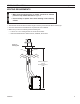
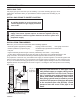
The command center may be mounted on the wall with
the use of the SCSWEK Kit (15ft. cable, junction box, wall
cover).
Mount the junction box provided at the desired location
on the wall. Do not extend beyond the 15 ft. wire cable
provided. If a longer distance is required, the 15 ft. may be
extended up to 30 ft. maximum by using two () SCSWEK
cables plugged together.
Route the wire from junction box to lower control area at
bottom of replace. Unplug the 1" cable from the com-
mand center. Attach the connector to the pins from wire
by pushing in to connector making sure to follow the color
code on connector. Plug the 15 ft. extension cable into the
ft. cable. Remove command center from the replace
and plug the other end of the extension cable into the
command center. Snap on wall cover provided and screw
to junction box.
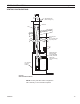
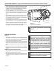
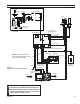
The wall switch wire connection is located off the ft. wire
harness from the control box to the command center. Fig-
ure 15. The connection is labeled “Wall Switch”. Unplug
the male and female connectors and connect the two ()
low voltage wires provided. Run wire to desired location
on wall. Up to 50 ft. of 18 ga. wire may be used if neces-
sary. Attach wires to wall switch. Mount the wall switch in
to junction box and screw on cover.
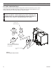
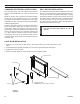
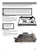
1. Remove front cover plate on light box by removing the three (3) screws securing the cover
plate.
. Install the halogen light bulb provided. Do not touch the light bulb directly with ngers.
3. Replace the front cover plate.
4. Slide the colored diffuser on top of the light box in the channel guides.
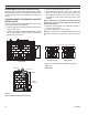
FP2682
light box
Figure 14 -
Light Box
Channel Guides
Colored Diffuser
Cover Plate
Screws
Halogen Light Bulb
( Do not touch with bare hands)
FP68