
Owner manual


7
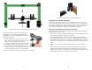
Counterbalance Carriage on left. Sliding Carriage on right.
To attach the carriages, remove the end pieces on the
Rotating Beam. As you look at the ruled side of the
Rotating Beam, you will attach the Sliding Carriage to
the right side as follows:
1. Note the sets of bearings upon which the carriage
slides. Two sets of bearings appear on the top of the
carriage and one set appears on the bottom.
2. As you slide the Sliding Carriage on the beam, orient
the carriage so that the end of the carriage with the
single bottom set of bearings slides on first. (See on
next page.) If you orient the carriage the other way, your carriage will not be able
to reach its maximum radius (~16 cm) on the beam.
3. Slide the Counterbalance Carriage on the other side of the beam.
8
Attaching the Sliding Carriage to the Rotating Beam
Using Sensors with the Apparatus
While investigating centripetal force with this apparatus, students use sensors to
measure force and angular velocity. Our recommendation is to use the Dual-Range
Force Sensor to measure force and the Vernier Photogate to measure angular speed.
The Vernier Wireless Dynamic Sensor System can also be used to measure force.
The following describes how to connect each sensor to the apparatus.
Attaching a Dual-Range Force Sensor to the Frame
A Dual-Range Force Sensor attaches to the right-hand vertical side of the apparatus.
Follow these assembly instructions.
1. In normal use, a hook or a bumper is attached to the end of the Dual-Range Force
Sensor. Remove the hook or bumper if it is attached.
2. Two pulleys are attached to the top of the frame. With the pulleys facing you,
attach the Dual-Range Force Sensor to the Force Sensor Bracket on the right side.
3. Thread the screw end of the Swivel Assembly over the middle pulley on the top
of the frame, then thread the screw end through the pulley on the right side of the
frame.
4. Attach the screw end of the Swivel Assembly to the force sensor, as shown
below.
5. Thread the loop end of the Swivel Assembly under the Pulley Guide near the
middle of the beam and attach the loop end to the Sliding Carriage, as shown in
the larger photo on page 7. The Sliding Carriage should be on the right side of the
Rotating Beam with the ruled side of the beam facing you.