LabPro Technical Reference Manual Calculator-Based Laboratory, CBL, CBL 2 , and TI-GRAPH LINK are trademarks of Texas Instruments Incorporated. LabPro is a registered trademark of Vernier Software & Technology. 2000 Vernier Software & Technology. All rights are reserved.
Revision Date: 08/02/02 Incorporated, with permission of the publisher. Contents ABOUT THIS MANUAL.............................................................................................................................5 INTRODUCTION.........................................................................................................................................5 PROGRAMMING LABPRO ...................................................................................................................
Revision Date: 08/02/02 COMMAND 10 COMMAND 12 COMMAND 102 COMMAND 115 COMMAND 116 COMMAND 117 COMMAND 201 COMMAND 401 COMMAND 1998 COMMAND 1999 COMMAND 2001 ADVANCED DATA REDUCTION .......................................................................................49 DIGITAL DATA CAPTURE ................................................................................................51 PORT POWER CONTROL COMMAND ................................................................................
Revision Date: 08/02/02 Example 11: Command 8 Program.........................................................................................................4 Example 12: Command 9 Program.........................................................................................................4 Example 13: Command 10 Program.......................................................................................................4 Example 14: Archive Program (Command 201) ......................................
Revision Date: 08/02/02 About This Manual This technical reference is intended for LabPro users who want to write their own programs for LabPro and computers or Texas Instruments graphing calculators. This document includes technical data such as syntax for LabPro commands, sample programs, error codes, specifications for sensors and miscellaneous other topics.
Revision Date: 08/02/02 be used at a time. The GraphLink port is used almost exclusively with a TI Graphing calculator while the USB and RS-232 ports are used with a computer. LabPro has six interface ports for data collection. The ports labeled CH1 through CH4 are used to collect analog data from sensors such as temperature, pH, force etc.
Revision Date: 08/02/02 In order to clear all settings, send a reset, 0 command. This command clears data collection RAM, channel assignments and data collection modes that are currently assigned in LabPro. This is a good first step to put LabPro into a known state before configuring the channels. However, this is not to say that a reset should always be sent to LabPro.
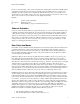
Revision Date: 08/02/02 • The communications with the host are turned off during sampling. Note: In FastMode sampling, it is very important that the program not issue any commands until after sampling has been completed. If LabPro receives any command, it will abort FastMode sampling with an error in order to respond to the command. Data Collection Mode Comparison Table The table below shows some of the differences between the data collection modes.
Revision Date: 08/02/02 Timebase Regardless of which type of data collection is used, the user must set the data collection rate based on the available rates offered by LabPro. The range of possible times between readings is from 16,000 seconds to 2 x 10⁻⁵ seconds for analog data collection with a single channel. With two analog channels read at the same time, the shortest sampling time is 2 x 10⁻⁴ seconds. The data collection mode used affects the sample times allowed with LabPro.
Revision Date: 08/02/02 on the calculator. • • • Calculator user can use the DataMate program to Save, Load and Delete data sets in the FLASH archive. This can be very useful for performing and retaining multiple experimental trials in the field. Directions for using this feature are given in the DataMate Guidebook. You can write a program to review the list of stored data sets and retrieve the desired one for further analysis. (See the sample archive program.
Revision Date: 08/02/02 now support an Auto-ID feature. By using a 1 for operation in this command, LabPro will automatically determine input configuration, conversion information as well as other sensor specific information. If no sensor is found during an Auto-ID process, it defaults to the 0 to 5V input. Using 14 is a more manual example. It is more common to exploit the AutoID feature.
Revision Date: 08/02/02 Many of these features may not be needed and left in their default state or set to zero. Here are the commonly used parameters: samptime = the time between samples (in seconds). The range is 0.00002 to 16000 seconds. numsamp = the number of readings to be made. This can be any integer from 1 to 12,000. (Numsamp = -1 puts LabPro into RT data collection mode as explained below.
Revision Date: 08/02/02 This type of data collection works great for many programs where you just want to monitor the reading from a sensor as you collect data and take action if it exceeds a certain specified value; for example, a program that turns on a fan if a temperature gets too high. Motion Detector Data Collection Programs for using motion detectors (also known as ultrasonic rangers) are somewhat like programs for using an analog sensor.
Revision Date: 08/02/02 send a Command 6: 6,0 This will terminate data collection while keeping intact the data buffer and the channel configuration. Keeping Power on During Analog Data Collection LabPro tries to minimize power consumption by turning power off to sensors when data is not being collected. There are some subtle issues involved with reading signals from sensors such as Vernier pH, Conductivity, Ion Selective Electrodes, Dissolved Oxygen, CO2, and Flow Rate.
Revision Date: 08/02/02 timing data from each of the LabPro channels and calculate the desired result. The continuous pulse mode (time gate is blocked) is used for several modes of timing. The following examples detail some common timing tasks. Timing how long a photogate connected to a DIG/SONIC port is blocked (Gate Timing) This timing mode is used to time pulses through a single photogate. The times reported to the user represent the duration of the photogate being blocked.
Revision Date: 08/02/02 Poll channel 1 for a new event. Once an event has occurred, poll for an event change on channel 2. Once this event occurs, retrieve the latest pulse widths from both these channels. 12,41,0 12,42,0 poll until you get a change in return value, store this in a variable, e.g., j After channel one event change is detected, poll channel two until you get a change in return value, store this in a variable, e.g.
Revision Date: 08/02/02 this would correspond to n=8 and m=10. If n and m are omitted, all events are returned. 12,41,-2,n,m Requests the start times of each period measurement. These two values are used to fill in the data table. Since the start times are referenced to the start of the experiment, the value for the first event should be subtracted from the times to get the first event starting at time t = 0. Radiation Monitoring Radiation counting is also set up using Command 12.
Revision Date: 08/02/02 12,41,-1,m,n returns data points starting with point m and ending at point n. Data is position of the rotary motion sensor, relative to its position when the data collection began. Digital Outputs The electrical characteristics of the digital outputs are: ♦ ♦ Voutput-high ≥3.7 V @ -400 uA Voutput-low ≤0.65 V @ 1.6 mA Using Command 2001 This is the simplest way to set the status of the digital output lines.
Revision Date: 08/02/02 Digital Output Buffer Example Command 1 list is {1,31,5,1,2,3,4,5} where: Command 3 list is {3,1,100} where: 1=Channel Setup. 3=Sample and Trigger Setup. 31=DIG OUT. 1=One second sample time. 5=Five data elements. 100=One hundred samples. 1=0001 (digital nibble). (Trigger Type defaults to manual triggering.) 2=0010 (digital nibble). 3=0011 (digital nibble). 4=0100 (digital nibble). 5=0101 (digital nibble).
Revision Date: 08/02/02 period = time (in milliseconds) to complete one cycle The DC output voltage is set by the equation: Vout = 2.4mV*amplitude – 1.2mV*offset The command 401,1,1024,1024,0 will output a 1.25V signal. To turn off the analog output: 401,0,0,0,0 When the analog output is off, the Vin line (pin 1) of CH4 line may be used as a ± 5 volt analog input. Note that this is different from the other three analog input channels.
Revision Date: 08/02/02 Computer Programming Basic communications Commands are sent using the following format: s{command number, parameter 1,…, parameter n} where the command number is required followed by one or more parameters that may or may not be required (see command reference section). Data is returned either automatically or by requesting data by sending: the character "g".
Revision Date: 08/02/02 the active channels, just as it does in the ASCII or calculator mode. For instance, with two channels active, the following would be returned: g (sent by host) Pt1_Ch1_MSB Pt1_Ch1_LSB Pt2_Ch1_MSB Pt2_Ch1_LSB ... PtN_Ch1_MSB PtN_Ch1_LSB Chk g (sent by host) Pt1_Ch2_MSB Pt1_Ch2_LSB Pt2_Ch2_MSB Pt2_Ch2_LSB ...
Revision Date: 08/02/02 One significant difference is that trying to read from USB will not return 0 bytes of data, like an empty serial port call. Instead, the call blocks until data is available from the LabPro. This occurs because LabPro sends a NAK (Not Acknowledge) response until data is valid. The device driver will then wait, blocking on the read, until the data is there. This means that the software read function will not return until the data is ready.
Revision Date: 08/02/02 When using LabPro in RT mode over USB, the number of bytes transmitted back is always 16 (see above information). For an unloaded USB bus (i.e. no other peripherals), we should have a limit of 1k samples per second for RT mode for 1 to 6 channels active. If you try to use RT at higher data rates, loss and corruption of data can occur. When the RT mode limit is exceeded, the software must switch to utilize the NRT mode of LabPro.
Revision Date: 08/02/02 where the first line stores the command number and parameters to the calculator list called listname, the second line actively sends the list called listname to LabPro and the third line retrieves the requested data from LabPro to variable on the calculator. • In the command list the command number is required followed by one or more parameters that may or may not be required. See the section titled LabPro Command Summary for details on the commands and their parameters.
Revision Date: 08/02/02 L1 will remain as they were prior to the “Get“ request. Since LabPro was prepared to return a 17-element status list on the next “Get“ request, and only a single list element was specified in that request, only the first in the status list was returned as data. If L1 was {1,2,3,4,5} prior to the “Get“; after the “Get“ it would be {1,6.0112,3,4,5}. “Get“ request with a real number: Send({7}) Get(A) In this case real number variable A was specified in the “Get” request.
Revision Date: 08/02/02 Calculator Limitations Calculator memory is an important factor to consider when collecting data with LabPro. Even though LabPro can store up to 12,000 points, if a calculator has insufficient memory when using a “Get” request, no data will be retrieved. Each element of a list, and therefore each data value takes up about 10 Bytes of calculator memory (regardless of the calculator) and calculator programs also occupy memory.
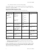
Revision Date: 08/02/02 LabPro Command Summary The table below lists the commands you can use in writing programs for LabPro. Command Number 28 Command Description 0 Reset: Resets all channels to default conditions. 1 Channel Setup: sets up a channel for data collection. 3 Data Collection Setup: Sets up the collection parameters for an experiment.
Revision Date: 08/02/02 201 Archive Operations Command: Allows the calculator to determine the contents of LabPro’s FLASH memory. 401 Analog Output Setup: This command sets up parameters to control the analog output driver in LabPro. 1998 Set LED Command: Turns LEDs on and off on command. 1999 Sound Command: Specifies length and frequency of LabPro sounds. 2001 Direct Output to Digital-Out Port: Outputs data to the digital output port. Detailed information about each command is given below.
Revision Date: 08/02/02 Command 0 Reset LabPro This command clears the data memory, error information, channel setup, and data collection information. Only the RAM is reset; FLASH memory is not cleared. Syntax: {0} Return values: No information is returned.
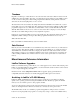
Revision Date: 08/02/02 Command 1 Channel Setup This command sets up a channel for data collection. Syntax: {1, channel[, operation[, post-proc, delta, equ]] } Parameter List: Channel – indicates channel on which this command operates.
Revision Date: 08/02/02 Delta Equ – used for internal debugging purposes and should always be set to zero (0). Post-Proc Value Description 0 Not used but required as a place holder if EQU is specified – indicates whether or not a conversion equation is applied to the data before it is returned. If Equ set to 1, Command 4 must be sent prior to data collection to specify the equation.
Revision Date: 08/02/02 Syntax: {1, channel, operation, list of values} Channel Operation 0 = Clears the channel 31 = Digital Output 1 32 = Digital Output 2 1-32 = Count (number of data elements in list) The list of values must have one value for each count. List of Values Values may be from 0 to 15. Example 5: Count down from 5. Note we set Channel 1 active. We don't have to retrieve the data.
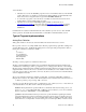
Revision Date: 08/02/02 The parameters shown in this table are used when measuring period or frequency. Trigger Type Edge Polarity Used Hardware Threshold Used 0 Rising (+) Trigger Threshold parameter 2–5 Specified by trigger type Trigger Threshold parameter 6 Not allowed (E.34 error). Measuring Frequency Assume a frequency measurement is requested on CH 1, and 20 measurements are desired at a .5 second sample time. The following commands would set up LabPro for this example: {1,1,6} {3,.
Revision Date: 08/02/02 Command 3 Data Collection Setup This command sets up the data collection parameters for an experiment. Syntax: {3,samptime[, numpoints, trigtype, trigchan, trigthresh, pre-store, extclock, rectime, filter[, fastmode]]} Parameter List: samptime – sets time between samples in seconds. The default sampling time is 0.5 second. The possible values are 0.00002 to 16,000 seconds. Samptime may also be –1 if the previous sampling needs to be repeated.
Revision Date: 08/02/02 pre-store – indicates how much data (as a percentage of all measurements to be made) prior to the triggering event should be stored. This value can be an integer between zero (0) and one hundred (100). For example, if pre-store is set to 10 with 1000 total measurements to be made, 100 data points made before the trigger event will be reported. extclock – used for internal debugging purposes and should always be set to zero (0).
Revision Date: 08/02/02 The THRESHOLD parameter specified in Command 3 can be used for two purposes: • If the operation in Command 1 is frequency, period, or count (operation = 5, 6, or 7 on Channel 1 only), then the threshold parameter in Command 3 sets a voltage level in LabPro hardware. The signal on the Vin pin of CH 1 must pass through this voltage for LabPro to see the signal change states.
Revision Date: 08/02/02 LabPro will collect and store a sample every 10 seconds. The recorded time for each sample will be 10 seconds. The trigger event (signal rising through 1.0 Volts) occurs 1.5 seconds after the previous sample, so a sample collected at the trigger point is taken and stored with a recorded time of 1.5. The next sample is taken 10 seconds after the trigger sample, not 8.5 seconds later as would have happened if the internal sample clock had not been reset.
Revision Date: 08/02/02 Command 4 Conversion Equation Setup (Analog) This command sets up parameters to convert physical units measured by LabPro into a more useful measurement unit such as newtons or °C. Syntax: {4, channel[, equtype[, K 0, K 1]]} Parameter List: channel – indicates channel on which this command operates.
Revision Date: 08/02/02 Return values: No information is returned. Example 1: Compensate motion detector for air temperature of 29°C. Computer Calculator Note s{4,11,13,84.2,1} :Send({4,11,13,84.2,1}) For °Fahrenheit temps. s{4,11,13,29,2} :Send({4,11,13,29,2}) For °Celsius temps. Example 2: Take 500 samples from Analog Channel 1 at 50,000/s in NRT mode and return the values in hexadecimal values. Computer Calculator Note s{0} :Send({4,11,13,84.2,1}) Reset the LabPro.
Revision Date: 08/02/02 Command 5 Data Control This command selects the type of data to be retrieved, as well as the starting and ending data points to be retrieved. This is the only command that requires “Get” statement to follow each Command 5 regardless of the host. Sampling must be completed before sending Command 5 to control the data. Before sending Command 5, do a Get statement to ensure that sampling is completed or send Command 7 to check the status and verify that sampling is completed.
Revision Date: 08/02/02 Computer s{5,1,3,0,0} g s{5,1,3,1,7} g 42 Calculator :Send({5,1,3,0,0}) :Get(L1) :Send({5,1,3,1,7}) :Get(L1) LabPro Technical Manual
Revision Date: 08/02/02 In a terminal session, the host-LabPro conversation appears as follows: Host LabPro s{0} s{1,1,14,0} s{3,0.02,11,0} g { +2.31502E+00, +2.31868E+00, +2.32234E+00, +2.32479E+00, +2.32723E+00, +2.21734E+00, +1.81319E+00, +1.48230E+00, +1.21368E+00, +9.92674E-01, +8.11966E-01 } s{5,1,3,0,0} g { +2.31502E+00, +2.31868E+00, +2.32234E+00, +2.32479E+00, +2.32723E+00, +2.21734E+00, +1.81319E+00, +1.48230E+00, +1.21368E+00, +9.92674E-01, +8.11966E-01 } s{5,1,3,1,7} g { +2.31502E+00, +2.
Revision Date: 08/02/02 Command 6 System Setup This command can be used to turn sound on or off, set an ID number for LabPro, and select a filter to be applied to data. Syntax: {6,syssetup[, parm]} Parameter List: syssetup – indicates which channel on which this command operates.
Revision Date: 08/02/02 Command 7 Request System Status This command returns LabPro’s 17 status registers. Syntax: {7} Return values: The following information is returned. Register Description softwareID Current software ID in format: X.MMmms where X=product code number, MM=major ID number, mm=minor ID number, and s=step ID number. error If non-zero, LabPro should be reset and the cause of the error corrected. battery Battery status.
Revision Date: 08/02/02 In a terminal session, the host-LabPro conversation appears as follows: Host LabPro s{0} s{7} { +6.01120E+00, +0.00000E+00, +0.00000E+00, +8.88800E+03, +0.00000E+00, +0.00000E+00, +0.00000E+00, +0.00000E+00, +0.00000E+00, +0.00000E+00, +0.00000E+00, +0.00000E+00, +0.00000E+00, +1.00000E+00, +0.00000E+00, +0.00000E+00, +0.00000E+00} s{4,2,5,0,1} s{7} { +6.01120E+00, +0.00000E+00, +0.00000E+00, +8.88800E+03, +0.00000E+00, +0.00000E+00, +0.00000E+00, +0.00000E+00, +0.00000E+00, +0.
Revision Date: 08/02/02 Command 8 Request Channel Status This command is used during data collection to read the operation or sensor type, the last valid data point and the number of samples collected. Calculators must use the “Get” command to retreive this information. Using this does not interfere with the active data collection. Syntax: {8,channel, reqtype} Parameter List: channel – indicates which channel on which this command operates.
Revision Date: 08/02/02 Command 9 Request Channel Data This command requests one data point before sampling starts. Used to verify that setup is correct. Syntax: {9,channel, mode} Parameter List: channel – indicates the channel on which this command operates. The possible values are Channel number Description 1–4 Analog channels 1 through 4 11, 12 Sonic Channel 1, Sonic Channel 2 mode – chooses between present setup or setup for previously collected run.
Revision Date: 08/02/02 Command 10 Advanced Data Reduction This command sets up LabPro to process certain time-intensive algorithms instead of processing them in the host. This allows large data sets to be processed much more quickly. Syntax: {10, channel, alg, P1, P2, P3} Parameter List: channel – indicates the channel on which this command operates. The possible values are Channel number Description 1–4 Analog channels 1 through 4 alg – algorithm to process..
Revision Date: 08/02/02 Example 1: Determine the frequency of a periodic signal on analog channel 1 from a 5000 point block of data collected at 50 points per second. P1 is set to 10% of the lower threshold, P2 is set to 10% of upper threshold and P3 is set to 0.5 volts. Computer Calculator s{1,1,14,0,0,0} :Send({1,1,14,0,0,0}) s{3,0.02,5000,0,0,0,0,0,0,0} :Send({3,0.02,5000,0,0,0,0,0,0,0}) s{10,1,1,10,20,0.05} :Send({10,1,1,10,20,0.05}) :Get(Rate) Freq = Rate / SampleInterval = Rate / 0.
Revision Date: 08/02/02 Command 12 Digital Data Capture This command sets up the capture of data from the digital input channels. The digital lines are electrically “pulled” high so that the LabPro digital lines have a default state. Each DIG/SONIC port consists of four digital lines. Command 12 reads a single line of each DIG/SONIC port. Figure 1 illustrates how the digital lines are physical mapping. When Command 12 is used, the power generally stays on during sampling.
Revision Date: 08/02/02 5 Counts transitions on the D0 input line of the Digital input port. This mode is used when the frequency of a source with a TTL (or CMOS compatible) output must be measured. Mode –1 will return a list of counts. Mode –2 is invalid in this context. Vernier Rotary Motion sensor. Generally this indicates the position of a wheel on the sensor. Mode –1 will return the position of the rotary motion sensor, scaled as indicated by P1 (see below). Mode –2 is invalid in this context.
Revision Date: 08/02/02 s{12,42,1} s{3,10,2,0} s{12,41,0} s{12,42,0} s{12,41,-2} s{12,42,-2} s{12,41,-1} s{12,42,-1} { { { { { { +2.00000E+00 } +2.00000E+00 } +2.40160E+00, +5.04500E+00, } +3.80320E+00, +5.92310E+00, } +0.00000E+00, +1.00000E+00, } +0.00000E+00, +1.60000E+01, } At each transition of the digital inputs, the absolute time and state of the inputs is reported (See Figure 3.) This command can be run at the same time as analog sampling.
Revision Date: 08/02/02 This mode is designed to measure the widths of pulses in a continuous stream of pulses. The Sonic Timer is used to record the time of the rising and falling edges. The resolution is 1.6 µsec. At the start of the pulse the time is recorded and again at the end of the pulse. The difference (properly scaled) is returned to the host. Continuous Pulse Mode may be used to measure either pulses in the high state as shown in Figure 4 or pulse in the low state.
Revision Date: 08/02/02 To illustrate it’s use, LabPro will be programmed to count pulses for five, one-second intervals while a super pulley spins down (the spokes block the photogate beam.) Host s{1,1,14} s{12,41,5} s{3,1,6,0} s{12,41,0} s{12,41,-1,0} LabPro { +5.00000E+00 } { +5.90000E+01, +4.80000E+01, +3.70000E+01, +2.70000E+01, +1.
Revision Date: 08/02/02 Command 102 Port Power Control Command This command controls how the LabPro powers the analog and DIG/SONIC ports. Syntax: {102,pwrctl} Parameter List: pwrctl – determines how power is used in LabPro pwrctl value Description -2 Always ON; will automatically power down if running on batteries. Leaves power to the sensor ports on at all times. 0 1 - 999 This is valid for LabPro version 6.06210 and newer.
Revision Date: 08/02/02 Command 105 Baud Rate Selection New in firmware version 6.06200, this command controls the baud rate of the RS-232 serial port. Only hard reset or {105,38} returns the baud rate to 38400. This command has no effect on calculators. Syntax: {105,baudrate} Parameter List: pwrctl – determines how power is used in LabPro baudrate Description value 38 38,400 baud 115 115,200 baud. Return values: An “OK” is returned when this command is received and just before changing timers.
Revision Date: 08/02/02 Command 106 Motion Detector Undersample Rate New in firmware version 6.06227, this command controls the rate at which motion detector data is collected while not effecting the rate at which analog data is collecting. This is also known as “Collision Mode” as an accelerometer can be read at a rate of 1000 per second and a motion detector at a rate of 10 per second. When collecting data this way, data at times between motion samples will have a value of 0.0000.
Revision Date: 08/02/02 Command 107 Oversampling Burst New in firmware version 6.06227, this command controls the oversampling of data for slower rates of data collection. Currently it works with all available analog channels and will not work if a sonic channel is enabled. For best results, the minimum allowed sample interval sent in Command 3 is 0.2 seconds per sample. Also, the duration of an oversampling burst should not exceed ½ of the sample interval sent in Command 3.
Revision Date: 08/02/02 Command 115 Request Set-up Information This command is only used to request the setup information for the Auto-ID sensor on a desired channel. Syntax: {115,channel} Parameter List: channel – indicates which channel on which this command operates. The possible values are Channel number Description 1–4 Analog channels 1 through 4 11, 12 Sonic Channel 1, Sonic Channel 2 Return values: The following information is returned.
Revision Date: 08/02/02 Command 116 Request Long Sensor Name This command returns the long sensor name in a format the calculator can handle. This command requires the channels of interest be initialized first with Command 1 (e.g., s{1,1,1}). This command is only used with an Auto-ID sensor on a desired channel. Syntax: {116,channel} Parameter List: channel – indicates which channel on which this command operates.
Revision Date: 08/02/02 Command 117 Request Short Sensor Name This command returns the short sensor name in a format the calculator can handle. This command requires the channels of interest be initialized first with Command 1 (e.g., s{1,1,1}). This command is only used with an Auto-ID sensor on a desired channel. Syntax: {117,channel} Parameter List: channel – indicates which channel on which this command operates.
Revision Date: 08/02/02 Command 119 Request Alternate Calibration This command returns the short sensor name in a format the calculator can handle. This command requires the channels of interest be initialized first with Command 1 (e.g., s{1,1,1}). This command is only used with an Auto-ID sensor on a desired channel. Syntax: {119,channel,altcalib} Parameter List: channel – indicates which channel on which this command operates.
Revision Date: 08/02/02 Command 201 Archive Operations Command This command allows the host to manage the contents of FLASH memory. The content of FLASH memory is semi-permanent in that it will not be altered unless the user chooses to do so. FLASH memory will remain in tact even if power to LabPro is lost. With this command one can store, retrieve or erase calculator programs, lists of data or entire data sets to and from the FLASH memory.
Revision Date: 08/02/02 operation Description operand 1 1 41 Select programs 10 Not used, set to zero (0) operand 2 1 (default = 1) Not used, set to zero (0) 42 Deselect programs 11 Retrieve supplemental programs12 Perform garbage collection† N/A N/A relinfolist 2 (default = 0 {all}) First item is calculator type (73, 83, etc.) followed by items to retrieve N/A N/A N/A N/A N/A N/A N/A 43 1001 Notes: 1 Operand information relating to whatever operation is being performed.
Revision Date: 08/02/02 • • • All data types are stored in LabPro directory in the same order in which they are received. LabPro does not attempt to sort these entries in any other order. If you transfer to LabPro a program with the same name as a program already in storage, the old program will be deleted and the new program will be added to the end of the directory. (A program with the same name but a different calculator model will not be affected.
Revision Date: 08/02/02 Example 1: Saving and Restoring a Data Set to FLASH memory IMPORTANT: Before performing any operation which writes or deletes items in the FLASH memory, it is very important to check that the battery level of LabPro is sufficient. Use command {7} to do so. Also, operations 21, 31, and 1001 may cause LabPro to automatically perform garbage collection on the FLASH memory.
Revision Date: 08/02/02 Command 401 Analog Output Setup This command sets up parameters to control the analog output driver in LabPro. The output voltage range is +/- 3 V with a current limit of 100 mA. The output voltage is determined by: Vout = 0.0024*amplitude – 0.0012*offset where the result must satisfy –3V < Vout < 3V The analog output is present on line 1 of CH4. Therefore the Voltage clips supplied with LabPro may be used to connect the analog output to external circuits.
Revision Date: 08/02/02 Syntax: {401, waveform, amplitude, offset, period} Parameter List: (note: all parameters are mandatory) waveform – indicates which waveforms will be generated. The possible values are waveform Description 0 OFF 1 DC Output 2 Ramp Up (Sawtooth) 3 Ramp Down (Sawtooth) 4 Triangle 5 Square 6 Sine amplitude – indicates which height of the wave. The possible values are from 0 to 4095. See Sine examples for exceptions. offset – indicates where the wave will be centered.
Revision Date: 08/02/02 Command 1998 Set LED Command This command causes LabPro’s LEDs to turn on or off. Syntax: {1998, P1, P2} Parameter List: P1 – indicates which LED to control The possible values are: P1 Color of Controlled LED 1 Red 2 Yellow 3 Green P2 – indicates the state of the LED- zero(0) for off and one(1) for on. Note: Leaving a LED turned on will run down the batteries in LabPro. Return values: No information is returned.
Revision Date: 08/02/02 Command 1999 Sound Command This command causes LabPro to vibrate its piezo speaker. The duration and frequency of the tones emitted from the LabPro’s speaker determine the tune. The time base for the duration and the frequency of the tones is 100µs. Syntax: {1999,length 1,Pd 1 ,length 2 ,Pd 2 , . . . ,length N ,Pd N } Parameter List: length – indicates the duration or how long the tone will be generated. The possible values are 1 to 255 in 100 µsec steps.
Revision Date: 08/02/02 Command 2001 Direct Output to Digital-Out Port This command outputs data to the digital output port during a sampling run, thus giving the user interactive control of some types of hardware using LabPro digital output lines. Please note the following: • • • • One to sixteen data points may be output. If more than one point is sent, all the points will be sent out at about 200 µsec intervals before the next command is parsed.
Revision Date: 08/02/02 LabPro Hardware Connector Pinouts LabPro sensors use 6-pin British Telecom-style connectors. Pin-1 is always farthest from the tab.
Revision Date: 08/02/02 Technical Specifications for LabPro General Specifications Power Requirements Power Connection Physical Dimensions Weight Environmental: Operating Temperature range Storage Temperature range Relative Humidity Analog Channels CH1 – CH4 Digital Channels DIG1, DIG2 Power at sensor connectors 6VDC reg, 600mA or 4AA Alkaline Batteries 2.1mm Power Jack, center negative 8.4" x 3.3" x 1.
Revision Date: 08/02/02 Analog Inputs (Cont.) DC Parameters Integral Nonlinearity Differential Nonlinearity Offset Error System noise AC Parameters +/- 0.5 LSB +/- 1 LSB (no missing codes) 1 LSB +/- 1 LSB Input Bandwidth: 0-5V input 50kHz (f3dB) Input Bandwidth: +/-10V input 5kHz (f3dB) * For the Ch4 +/-5V input, use the +/- 10V input AC and DC parameters.
Revision Date: 08/02/02 LabPro Sensor Details Voltage Sensor The voltage sensor is a generic sensor that you can use to read any voltage between ±10 Volts. The autoID resistor contained in the sensor causes LabPro software to automatically measure voltage. No conversion equation is loaded. The black hook should be connected to ground and the red hook to the signal voltage.
Revision Date: 08/02/02 inside LabPro unit to convert current to voltage; this must be done in the external probe. 3 Default units for the Stainless Steel and TI Temperature sensors is °C. Channel 11 and 12 (SONIC) 1 IDENT Value 1 Sensor Type Range 15K Motion detector, meters 0.4 meter to 6 meters 22K Motion detector, meters 0.4 meter to 6 meters 10K Motion detector, feet 1.4 feet to 18 feet IDENT values are resistance values in ohms (tolerance ±5%).
Revision Date: 08/02/02 Appendix A: Glossary The following terms are used in LabPro documentation. Term A-1 Definition accuracy The degree of conformity of a measure to a standard or a true value archive Store data or programs in the FLASH memory of LabPro. (See page 9.) auto-ID Automatic Identification. Feature that allows LabPro to automatically identify specific sensors when they are connected to a LabPro channel.
Revision Date: 08/02/02 Appendix B: Beeps, Lights and Errors Beep and Light Sequences LabPro makes use of three LED indicators and four kinds of sounds: • A red LED (error indicator). • An amber LED (warning indicator). • A green LED (ready indicator). • A low tone followed by a high tone (low-to-high beep). • A medium tone followed by another medium tone (medium-medium beep). • A high tone followed by another high tone (high-high beep). • A “tick” sound when a key is pressed.
Revision Date: 08/02/02 • During base code download, three high-high beeps sound when any errors occur. (The unit resets and then the two high-high beeps mentioned in the previous bullet sound.) Error Codes In almost all cases, an error result causes the unit to sound the “low tone” three times and to illuminate the red LED three times. When this happens, send the request for status message and then observe the “error” code of the list returned.
Revision Date: 08/02/02 Error Code Error Cause mode and 0, 7, 8, or 9 for real time data collection mode. This error results from a filter selection outside of this range. 31 Command 3 was sent prior to performing any channel setups. 32 Sample time must be greater than 0 and less than 16000 seconds. The value is normally rounded to the nearest 100 µsec, but can be rounded to the nearest 50 µsec in FASTMODE. If the selected channels cannot support the rate selected, a slower sample rate will be used.
Revision Date: 08/02/02 Error Code B-4 Error Cause 55 The end-of-data selector must be 0 (for end of data) or 1 through the number of points collected. A number outside of this range will produce this error message. In addition, the end of the data must not be before the beginning of the data. 59 Digital probe has failed to read or write as commanded by the host. 61 An attempt has been made to collect more data than can be stored in one data collection.
Revision Date: 08/02/02 Error Code Error Cause data can be archived. 88 This error results when an attempt is made to archive data during sampling. Archive operations must occur only when the unit is idle. 97 This error indicates an attempt to use a channel that does not exist on LabPro (for example, channel 42). 98 This error indicates an undefined error has occurred.
Revision Date: 08/02/02 Appendix C: DataMate Sensor Setup Default Settings The table that follows shows the default settings used by the DataMate program. This sensor and calibration information applies only to Vernier and TI sensors. The use of other manufacturers’ sensors may require calibration or the input of that sensor’s calibration information into DataMate. Note: Default settings apply only when using a single sensor that is connected to Channel 1.
Revision Date: 08/02/02 Sensor Name Pressure (KPA) Short Name PRESS (KPA) Y-Min Y-Max Sample Interval (in seconds) No. Of Samples 0 700 1 180 Pressure (ATM) PRESS (ATM) 0 700 1 180 Pressure (MMHG) PRESS (MMHG) 0 5200 1 180 Bio Pressure (KPA) PRESS (KPA) 76 156 10 90 Bio Pressure (MMHG) PRESS (MMHG) 550 1200 10 90 Bio Pressure (ATM) PRESS (ATM) 0.75 1.6 10 90 Bio Pressure (INHG) PRESS (INHG) 20 50 10 90 Dual R Force (5N) FORCE(N) -5 5 0.
Revision Date: 08/02/02 Sensor Name Short Name Y-Min Y-Max Sample Interval (in seconds) No. Of Samples TI Light Sensor LIGHT 0 1 0.05 180 Light 600(LX) LIGHT(LX) 0 600 0.05 180 Light 6000(LX) LIGHT(LX) 0 6000 0.05 180 Light 150000(LX) LIGHT(LX) 0 150000 0.05 180 D. Oxygen (MG/L) DO(MG/L) 4 12 2 60 EKG EKG -0.5 4 0.
Revision Date: 08/02/02 Sensor Name Short Name Y-Min Y-Max Sample Interval (in seconds) No.
Revision Date: 08/02/02 Appendix D: Computer Programming Examples These programs were created in Microsoft Visual Basic 6.0 to set up specific LabPro operations. Samples of various types of programs follow. Each program includes both program commands and comments explaining what the commands do. General Structure of a VB Program Labpro.Output = "s{0} + vbCrLf resets LabPro (clears RAM) Labpro.Output = "s{1,……}" sends the initialize command to set up collection Labpro.
Revision Date: 08/02/02 Private Sub Form_Load() LabPro.PortOpen = True LabPro.Settings = "38400,N,8,1" End Sub your forms load event opens the Comm port sets the proper settings for LabPro Private Sub cmdCollect_Click() LabPro.Output = "s{0}" + vbCrLf LabPro.Output = "s{1,3,1}" + vbCrLf LabPro.Output = "s{3,1,-1}" + vbCrLf your button's click event reset LabPro (clears RAM) set up channel 3 for collection take sample every second, re-arms, and fires again End Sub Private Sub cmdStop_Click() lstInput.
Revision Date: 08/02/02 Private Sub Form_Load() LabPro.PortOpen = True LabPro.Settings = "38400,N,8,1" End Sub your forms load event opens the Comm port sets the proper settings for LabPro Private Sub cmdSend_Click() your button's click event LabPro.Output = "s{0}" + vbCrLf reset LabPro (clear RAM) LabPro.Output = "s{1,31,16,0,1,2,3,4,5,6,7 sets up Channel 31 to output the listed ,8,9,10,11,12,13,14,15}" + vbCrLf values to digital in source LabPro.Output = "s{3,0.5,10,0}" + vbCrLf every 0.
Revision Date: 08/02/02 inputvalue = Mid(labpro.Input, 5, 4) Else REM the exponent is not zero REM input value is equal to 4.40904 ^ 00 range = "." + Mid(labpro.Input, 5, 4) ^ Mid(labpro.Input, 15, 1) End If If you are using negative numbers you will need to add If statements to check if the 4th and 13th characters are "+" or "-". (Mid(labpro.Input, 4,1) and Mid(labpro.
Revision Date: 08/02/02 Appendix E: Calculator Programming Examples Although you can create and edit your programs using the calculator keypad, calculator programs are most easily dealt with on a computer using the TI-GRAPH LINK software (available from www.ti.com/calc). Once written, the program can be transferred to the calculator via a TI-GRAPH LINK cable (available from Vernier Software). Samples of various types of programs follow.
Revision Date: 08/02/02 =RRP6WDW Example 4: Multiple Channels Non-Realtime Data Collection 3ORWV2II &OU$OO/LVWV &OU+RPH 6HQG ^ ` 6HQG ^ ` 6HQG ^ ` 6HQG ^ ` 6HQG ^ ` 6HQG ^ ` *HW / *HW / *HW / *HW / 3ORW 6FDWWHU / / =RRP6WDW 3DXVH &OU+RPH 3ORWV2II 3ORW 6FDWWHU / / =RRP6WDW 3DXVH &OU+RPH 3ORWV2II 3ORW 6FDWWHU / / =RRP6WDW Reset LabPro. (This clears LabPro RAM.) Turn LabPro sound on.
Revision Date: 08/02/02 6HQG ^ ` *HW / *HW / 6HQG ^ ` *HW / Take a sample every .1 second, 100 times. Retrieve temperature in Fahrenheit data to L2. Retrieve time data to L1. Process temperature data 35 through 45 for retrieval. Retrieve temperature data 35 through 45 to L3. Example 7: Digital In Data Collection &OU$OO/LVWV &OU+RPH 6HQG ^ ` 6HQG ^ ` 6HQG ^ ` 6HQG ^ ` *HW / *HW / 'LVS / 'LVS / Reset LabPro. (This clears LabPro RAM.
Revision Date: 08/02/02 . . . . . . . . . . . . . . . . . . . . . . .` / ^ ` / )RU 1 6HQG ^ / 1 / 1 ` (QG ones for 0.3 seconds. Enter each note value in the list. Send each time and note to LabPro so that it can play every note in the order of the lists.
Revision Date: 08/02/02 $ % 'LVS % Divide the edges per sample by the sample time. This returns true frequency (edges per second). Display the frequency. Example 14: Archive Program (Command 201) This program stores and retrieves a data set.