
Instruction Manual

Revision Date: 08/02/02
LabPro Technical Manual 35
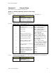
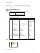
Command 3 Data Collection Setup
This command sets up the data collection parameters for an experiment.
Syntax:
{3,
samptime[, numpoints, trigtype, trigchan, trigthresh, pre-store,
extclock, rectime, filter[, fastmode]]
}
Parameter List:
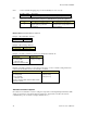
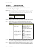
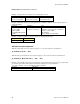
samptime – sets time between samples in seconds. The default sampling time is 0.5 second. The possible
values are 0.00002 to 16,000 seconds. Samptime may also be –1 if the previous sampling
needs to be repeated. Each probe has a minimum sample time, which is listed in the table
below:
Probe Type Minimum Sample Time
Analog probes
100
µ
sec per probe
20
µ
sec per probe in FastMode
Sonic probes 8 milliseconds
Digital In/Out
200
µ
sec per channel
numpoints – indicates the number of data points per input should be recorded. The possible values are 1 to
12,287. A value of zero is invalid. Setting this value to –1 puts LabPro into real-time data
collection mode.
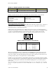
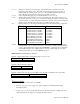
trigtype – indicates what events must occur on the Trigger Channel (trigchan) to start sampling.
Pressing the START/STOP button will circumvent triggered data collection. The possible
values are
trigtype Value Trigger Type Exceptions
0 Immediate May not be used with frequency
measurements or with period
measurements.
1 Manual (default) May not be used with frequency
measurements, with period
measurements or with FASTMODE
sampling.
2 Rising edge / Rising edge May not be used with transition
counting.
3 Falling edge / Falling edge May not be used with transition
counting.
4 Rising edge / Falling edge May not be used with transition
counting.
5 Falling edge / Rising edge May not be used with transition
counting.
6 Single sample May not be used with frequency
measurements, with period
measurements, with FASTMODE
sampling or with transition counting.
trigchan – indicates on which active channel the trigger conditions occur. Possible values are - zero (0)
for no triggering; one (1) for hardware triggering on analog channel 1; two (2), three (3) or
four (4) for software triggering on analog channels 2, 3 or 4; and 11 or 12 for DIG/SONIC1
or 2.
trigthresh – indicates the trigger threshold of the channel measured by the sensor attached to the trigger
channel. The type of the value used here is a float and must be within the measurable limits
of the channel.