
Instruction Manual


Revision Date: 08/02/02
LabPro Technical Manual52
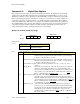
5 Counts transitions on the D0 input line of the Digital input port. This mode is used when the
frequency of a source with a TTL (or CMOS compatible) output must be
measured. Mode –1 will return a list of counts. Mode –2 is invalid in this
context.
6 Vernier Rotary Motion sensor. Generally this indicates the position of a wheel on the
sensor. Mode –1 will return the position of the rotary motion sensor,
scaled as indicated by P1 (see below). Mode –2 is invalid in this context.
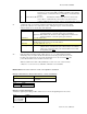
P1 –During the setup of a mode this parameter can indicate the desired direction of the digital
signal or the scale factor of a rotary motion sensor. During the request of a block of data this
indicates which row is to be the start of the data block.
Direction Use (only with mode 2 or 3)
0
Low Active Pulse width is the time between a high-low transition and the next
low-high transition, or the time a photogate is un-blocked.
1 High Active Pulse width is the time between a low-high transition and the next
high-low transition, or the time a photogate is blocked.
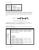
Scale Factor Use (only with mode 6)
0
Low Resolution rotary motion.
1 High Resolution rotary motion (4 x Low Resolution).
Data Start Use (only with mode –2 or –1)
0
or integer N.
Start indicates which data point (or row) the data block should start at. Any integer
value from zero to the last data point collected may be used. If this
value is zero (0), the first data point collected will be used to mark
the beginning of the data.
P2 – Only used when requesting a block of data (mode of –2 or –1). This parameter indicates
which data point (or row) the data block should start at. Any integer value from zero to the
last data point collected may be used. If the default value of zero (0) is used, the last data
point collected will be used to mark the end of the data.
When used with mode 6, P2 is a Reset Inhibit (0 = count is reset to 0 on each new data
collection, 1 = count is not reset.) Valid first on firmware version 6.06228.
Return values: The value returned is result of the algorithms calculation.
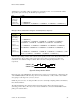
Example 1: Determine how many transitions have occurred on the D0 line.
Computer Calculator
s{12,41,0}<CR> :Send({12,41,0})
:Get(CNT)
Host LabPro
s{12,41,0} { +1.71000E+02 }
Example 2: Sample Digital Inputs
To illustrate digital input sampling, LabPro will be told to monitor both digital inputs for 10 seconds.
Host LabPro
s{0}<CR>
s{1,1,14,0}<CR>
s{12,41,1}<CR>