
Instruction Manual


Revision Date: 08/02/02
LabPro Technical Manual54
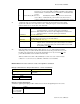
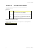
This mode is designed to measure the widths of pulses in a continuous stream of pulses. The Sonic Timer
is used to record the time of the rising and falling edges. The resolution is 1.6
µ
sec. At the start of the
pulse the time is recorded and again at the end of the pulse. The difference (properly scaled) is returned to
the host. Continuous Pulse Mode may be used to measure either pulses in the high state as shown in Figure
4 or pulse in the low state. This is chosen by setting the start parameter to 1 or 0, respectively.
Digital/Sonic (D0)
∆
T
∆
T
Figure 4. Continuous Pulse Period Measurement
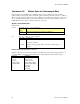
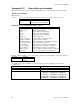
Example 4: Period measurement
Host LabPro
s{1,1,14}
s{12,41,4}
s{3,10,2,0}
s{12,41,0} { +0.00000E+00 }
s{3,-1}
s{12,41,0} { +2.00000E+00 }
s{12,41,-2,0} { +2.20510E+00, +5.36730E+00, }
s{12,41,-1,0} { +2.20506E+00, +3.16224E+00, }
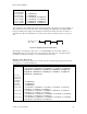
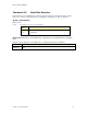
This mode is designed to measure the periods of pulses in a continuous stream of pulses. The period of the
pulse stream is measured beginning with either a high to low transition as shown in Figure 5 or a low to
high transition. This is chosen by setting the P1 parameter to 1 or 0, respectively. The Sonic Timer is used
to record the time of the rising and falling edges. The resolution is 1.6 µsec. At the start of the pulse the
time is recorded and again at the end of the pulses. The difference (properly scaled) is returned to the host.
∆
T
Digital/Sonic (D0)
∆
T
∆
T
Figure 5. Continuous Pulse Period Measurement
To illustrate the point, LabPro will be set to measure period of the pulses on the photogate connected to
DIG/SONIC1 port. On the first pass, the photogate will transition from unblocked to blocked during the
ten second sample period which should produce no samples because no complete cycles were completed.
The second pass shows two periods were measured when the photogate was twice blocked and unblocked
and finally blocked. Finally, the times that all the transitions began are retrieved with the {12, 41,-2,0}
command and the all the period lengths are returned with the {12,41,-1,0} command.
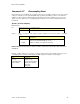
Example 5: Counter Mode using the command {12,41,5}
This mode is designed to count the transitions on the DIGITAL input line. The D0 line must be used for
the input. The Sonic Timer is re-configured as a counter and will count the input transitions. The
transitions count is limited to 65535 transitions per cycle. The cycle time is the same as the sample time. In
other words, one count will be returned for each analog sample returned.