
Install Guide


1414
2
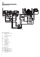
WIRING DIAGRAM
Tl1
N/7
1
2
1a
2a
L/8
1
6
P1
P6
4
P4
3
8
P3
P8
2
7
P2
P7
5
P5
F1
C
CIR
S
G
V
LF
M
T
CF
TM
S1
PR
S3
F2
F3
F4
F5
S1
S2
4
4a
P1
P2
2
S1
S2
4
P1
P2
2
CR
P2
H
S
2
4
P1
H
S
2
4
P4
H
S
2
4
P5
H
S
2
4
S1
S2
4
Pilot
P1
P2
2
S1
S2
4
P1
P2
2
Pilot Pilot
S1
S2
4
P1
P2
2
Pilot
P3
4
4A
S H
2
F6
V
CIR
Tl1
LF
S2
TS
ELECTRIC DIAGRAM KEY
Tl1 Cooling fan Thermolimitator
CF Cooling fan
TS Security thermal overload
M Terminal block
T Hearth plant
OVEN
F1 Oven switch
TM Oven thermostat
PR Programmer
TL Thermal overload
LF Oven lamp
S1 Thermostat pilot lamp
C Top element
G Grill element
CIR Circular element
S Fan
V Bottom element
VETROCERAMIC HOB
F2/3/5/6 Energy regulator switch
F4 Energy regulator switch ( dual )
P1/2/4/5 Radiant element
P3 Radiant element ( double )
CR Residual heat lamps group
S3 Line pilot lamp