
Install Manual


1111
1
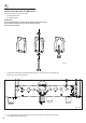
Fig. 1.11
=
=
Dotted line showing the position
of the range when installed
17”
15/16
(455.5 mm)
Anti-tip stability
device
Adjustable
bracket with
threaded nut
correctly tted
Anti-tip stability
device xing
3. Fix the stability bracket in place. It can be
xed as follows:
• To the oor OR on the rear wall by #4
screws (supplied).
• To the oor AND on the rear wall by #8
screws (supplied).
• There are 8 x wood screws and 8 x
screws with plastic
sleeve anchors supplied with the range
in two separate kits.
Use the proper screws according to
the type of material on the oor and/
or wall.
• If using the the plastic sleeve anchors: drill
5/16” (8mm) diameter holes and insert the
supplied plastic sleeve anchors before
attaching the stability bracket with the
screws.
4. Slide the range into place, ensuring the bolt
on the adjustable bracket slots under the
stability bracket.
• Adjust the length of the bolt as necessary.
Ensure the two nuts are well tightened after
any adjustments.
IMPORTANT!
• Use the proper screws to x the stability
bracket in place
according to the type of material on the
oor and/or wall.
• Before drilling and holes or inserting any
screws into the
oor or wall check that you will not
damage any wiring or
pipes.
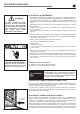
WARNING
- Slide range back so bolt head, on the adjustable bracket assembly, is
-under anti-tip bracket.
- Look for the anti-tip bracket securely attached to oor or wall.
- See installation instructions for details.
- Look for the adjustable bracket assembly securely attached to
-the back of the range.
- Slide range forward.
To verify the anti-tip bracket is installed and engaged:
Tip-Over Hazard
Anti-tip bracket
Adjustable bracket
assembly to be xed to
the back of the range
A child or adult can tip the range and be killed.
Install anti-tip device to range and/or structure per installation
instructions.
Engage the range to the anti-tip device Installed to the structure.
Re-engage anti-tip device if range is moved.
Failure to follow these instructions can result in death or serious
burns to children and adults.