
Installation Instructions


10
1
YOU MUST USE STABILITY
ANTI TIP BRACKET TO
PREVENT UNIT FROM
TIPPING.
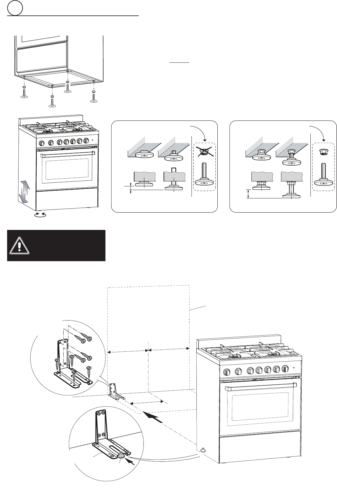
ANTI-TIP STABILITY DEVICE INSTALLATION INSTRUCTIONS
1. Theanti-tipbrackethastobeattachedasshownongurebelow(onlyrearleftside),
ithastobexedontheoorORontherearwallbyno.4(four)suitablescrews(not
supplied).Alternativelytheanti-tipbracketcanalsobexedontheoorANDonthe
rearwallbyno.8(eight)suitablescrews(notsupplied).
2. Afterxingtheanti-tipbracket,sliderangeintoplace.Besuretherearleftfootslides
undertheanti-tipbracketattached.
LEVELLING THE RANGE
Therangeisequippedwith4LEVELLINGFEETandmaybelevelledbyscrewingor
unscrewingthefeet(gs.1.6-1.7).
Itisimportanttoobservethedirectionsofgures1.6,1.8a,1.8b.
Fig. 1.8bFig. 1.8a
Fig. 1.7
Fig. 1.6
Suppliedwiththerange
inaseparatekit
Suppliedwiththerange
inaseparatekit
0”
0mm
+5/16”
+8mm
+5/16”
+8mm
+11/16”
+17.5mm
Fig. 1.9
Dotted line showing the position
oftherangewheninstalled
ANTI-TIPSTABILITY
DEVICEFIXING
Anti-tipstability
device
Rearleft
feetofrange
3”
15/64
(82mm)
=
=