UNIVERSAL ASSEMBLY INSTRUCTIONS FOR VERTICALLY SHEETED GARAGE BUILDINGS BUILDING WIDTHS: 12’, 20’, 24’, AND 30’ SINGLE DOOR GARAGE AVAILABLE IN 12’, 20’, 24’ AND 30’ WIDTHS DOUBLE DOOR GARAGE AVAILABLE IN 24’ AND 30’ WIDTHS Our unique assembly process quickly transforms the individual pieces into a finished structure that will give you years of service. Great care has been taken to ensure complete satisfaction with your purchase.
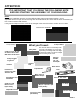
ABOUT OUR BUILDINGS Buildings come in four widths: 12’, 20’, 24’, and 30’. Buildings come in three side or eave heights: 8’, 10’, or 12’. Height extensions are required to create 10’ and 12’ side height buildings. 2’ height extensions for 10’ and 4’ height extensions for 12’. Buildings are supplied with 4’,5’ or 6’ on center post spacing depending on the requirements for wind and snow load in your area of the country.
ATTENTION: IT IS IMPORTANT THAT YOU READ THE FOLLOWING NOTE BEFORE STARTING THE ASSEMBLY OF YOUR BUILDING NOTE: If during the installation process you have difficulty fitting frame components together, use an adjustable wrench to open end of receiving tube as shown below, left. Close wrench down around bent portion of tube and bend wall outward. It may also be helpful to hit the center of the swaged at the end of the tube to create more of a lead.
BASIC PARTS LIST: SIZES AND QUANTITIES WILL VARY BY BUILDING WIDTH AND LENGTH SEE THE PACKING SLIP WITH YOU BUILDING FOR PART NUMBERS AND QUANTITIES.
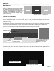
STEP 1: FOUNDATION CHECK WITH YOUR LOCAL BUILDING OFFICIAL BEFORE YOU POUR A SLAB OR ANCHOR YOUR BUILDING. We recommend that you have a concrete slab poured as a foundation for your building. A foundation drawing is included with the assembly instructions. If you choose to mount the building to an existing slab, the slab should be larger than the outside building dimensions by at least 3” front to back and 6” side to side.
STEP 3: ROOF/WALL FRAME ASSEMBLY On the ground, assemble (1) peak, (2) rafters, (2) side posts, and (2) height extensions if required. (10’ or 12’ side height buildings require 2’ or 4’ height extensions.) Before you fasten the joints with screws take a measurement across the top and bottom of the assembly as shown. This outside measurement is the outside size of your building. (12’, 20’, 24’, or 30’) Try to keep the joint spacing on both sides of the assembly equal.
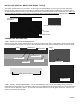
BRACING: TYPE (1) COLLAR TIE, TYPE (2) COLLAR TIE WITH VERTICAL, TYPE (3) COLLAR TIE WITH WEB BRACES Bracing on buildings is determined by the width of the building and the wind and snow load in your county. 12’ wide buildings do not normally require a truss brace. 20’ wide buildings may or may not require a brace. 24’ and 30’ wide buildings always require a truss brace.
INSTALLING VERTICAL BRACE FOR BRACE TYPE (2) The Center Vertical Brace is 1 1/2” square x 25 1/4” long on 20’ wide buildings, 31 1/4” long on 24’ wide, and 40 1/4” long on 30’ wide. Fasten the brace to the Collar Tie and the Frame Peak with Single Purlin Brackets. Use two screws in the bracket tongue and one screw in each side flange as shown. Fasten the brackets to the vertical brace first. Make sure that the Collar Tie assembly is straight before you fasten the brace to the Collar Tie and Peak.
STEP 3: INSTALL WEB BRACE 2: (On 20’ buildings 24”) (On 24’ buildings 30”) (On 30’ wide buildings 36”) Loosely attach Web Bracket 2 to the other end of Web Brace 1. Place the Web Bracket on the Collar Tie (make sure the collar tie is straight and fasten the face of the bracket to the collar tie with a self-drilling screw. Remove the hex nut and attach one end of Web Brace 2 to the Web Bracket 2 assembly.
STEP 4: INSTALLING ROOF/WALL FRAMES TO BASE RAILS NOTE: This assembly will require at least two people. 24’ and 30’ frames may require more. Start at one end of the building and place a Roof/Wall assembly, with no truss brace, on the first base rail vertical pins. Fasten joints with two screws each. Keep the screw heads away from the outside of the building where sheet metal will be installed. Repeat this assembly until all Roof/Wall assemblies are installed.
STEP 5: INSTALLING BACK BASE RAILS The Back Enclosure is the frame components that enclose the back of the building. Layout the Base Rail components as shown in the illustration of your building size. Note that all back frame components are 2” x 2” square tubing. See illustration below for length dimensions of base rail tubes. The base rail assembly is made up of straight length 2” square tubes and T-Connectors.
STEP 7: INSTALLING FRONT BASE RAILS AND VERTICALS GARAGE DOORS: THE BASIC GARAGE BUILDING COMES WITH 1 GARAGE (OR OVERHEAD) DOOR OPENING. 24’ AND 30’ WIDE BUILDINGS CAN ALSO HAVE AN OPTIONAL DOUBLE DOOR OPENING. DOOR SIZES: 12’ Wide-9’ Door, 20’ Wide-16’ Door, 24’ Wide-16’ or (2) 9’ Doors, 30 Wide-16’ or (2) 9’ Doors Find the illustration that matches your building size and door style. Join the Base Rail tubes and (L) or (U) connectors as shown. The Base Rails are all 2” square tubes.
INSTALLING FRONT ENCLOSURE CONTINUED VERTICAL HEADER BRACE 8’ HIGH 2” X 2” X 41 1/2” 10’ EIGH 2” X 2” X 65 1/2” 12’ HIGH 2” X 2” X 89 1/2” HEADER TUBE WITH ONE END SWAGED 2” X 3” X 81 3/4” FLAT BRACKET (3 PLACES) HEADER BRACE TO PEAK VERTICAL (DOOR JAMB) 2” X 3” X 86 1/4” (2 PLACES) DOOR HEADER 2” X 3” X 37” ANGLE BRACKET (6 PLACES) HEIGHT EXTENSION 2’ FOR 10’ HIGH GARAGE 2” X 3” X 28 3/4” (1) SWAGE 4’ FOR 12’ HIGH GARAGE 2” X 3” X 52 3/4” (1) SWAGE NONE ON 8’ HIGH GARAGE 7’ or 16’ L-CONNECTOR (2 PLAC
INSTALLING FRONT ENCLOSURE CONTINUED VERTICAL HEADER BRACE 8’ HIGH 2” X 2” X 50 1/2” 10’ HIGH 2” X 2” X 74 1/2” 12’ HIGH 2” X 2” X 98 1/2” HEADER TUBE WITH ONE END SWAGED 2” X 3” X 81 3/4” FLAT BRACKET (3 PLACES) HEADER BRACE TO PEAK VERTICAL (DOOR JAMB) 2” X 3” X 95” (2 PLACES) DOOR HEADER 2” X 3” X 37” ANGLE BRACKET (6 PLACES) HEIGHT EXTENSION 2’ FOR 10’ HIGH GARAGE 2” X 3” X 28 3/4” (1) SWAGE 4’ FOR 12’ HIGH GARAGE 2” X 3” X 52 3/4” (1) SWAGE NONE ON 8’ HIGH GARAGE 7’ or 16’ L-CONNECTOR (2 PLACES)
STEP 8: ASSEMBLE SIDE WALK DOOR FRAME AND OPTIONAL WINDOW FRAME The Door Frame consists of a Header Tube 2” x 3” x 45 3/4” long (for 4’ OC) or 57 3/4” long (for 5’ OC) 69 3/4” (for 6’ OC) and a Door Jamb 2” x 3” x 81 3/4”. These combine with the side post to create a 38” x 81 3/4” rough opening for your door. Note: If your building is on a slab, the base rail can be cut out at the door opening to prevent a trip hazard. If you will cut out the base rail use a reciprocating saw with a metal cutting blade.
INSTALLING THE WALK DOOR Pre-hung walk doors are typically attached to the frame with screws through the door jamb into the building frame on both sides. Some doors are flange mounted on the face of the door frame to the building with pan head screws and some doors are a combination of the two. Place your door in the opening with the front edge of the door flush or touching the outside of the nailer tubes and attach the door to the frame according to door manufactures instructions.
OPTIONAL WINDOW FRAME If you are installing an optional window frame, Measure your window to determine the rough opening that you will need. Cut the vertical window frame tubes to the height of the rough opening. Mount the lower horizontal window frame tube to the side posts as shown at right with angle brackets. The tube should be level. Pre-mount angle brackets to the vertical frame tubes. Center and properly space them on the bottom tube to give you the correct rough opening width. Fasten them in place.
STEP 9: INSTALLING HAT CHANNEL ON ROOF AND SIDES OF BUILDING The purlins on the roof and the girts on the sides of you building are Hat Channel. Most of the hat channel that you install will be 8’ long on buildings with frame sections on 4’ centers or 10’ long for buildings on 5’ centers and 12’ long on buildings on 6’ centers.. See the chart below for the location and dimensions for the Hat Channel on the roof and sides of the building.
As you install hat channel the building frame will gain stiffness and strength. It is important that you check the frame sections with your level for plumb as you install each hat channel. You may want to clamp a corner diagonal brace to the frame at the front or back of the building on both sides to hold the first frame section square. Measure from the first frame section to get the remaining sections plumb. 1.
4. Cutting hat channel girts around side wall walk door: You can use a hack saw to cut the hat channel, but it will be easier if you use an abrasive disk or metal cutting blade in a circular or miter saw to make the cuts. Remember to wear your eye protection and with power saws ear protection is recommended.
5. INSTALLING HAT CHANNEL AROUND WINDOW OPENINGS When you get to a window frame with a run of hat channel, you will have to measure and cut the channel to fit around the window frame. From an 8’ or 10’ piece of hat channel you must cut a short piece of channel to fit from the outside of the vertical nailer to the center of the side post and a longer piece of channel to fit from the outside of the other vertical nailer to the center of the second side post. See illustration below.
STEP 10: INSTALLING GIRTS ON FRONT AND BACK OF BUILDING Girts on the front and back of the building are 1 1/2” square tubes. (see illustrations of your building size for girt lengths.) Girts will be attached to the frame with two types of brackets: Single Brackets, which are used to attach girts at the corners of the building or any location when the girt does not continue on the other side of a vertical post.
GIRTS ON BACK OF BUILDING ALL GIRTS ON THE END WALLS ARE 1 1/2” SQUARE TUBE.
GIRTS ON FRONT OF BUILDING NOTE: All girts are 1 1/2” square tube. THE GIRTS ON THE FRONT OF THE BUILDING SHOULD BE AT THE SAME HEIGHTS AS THE GIRTS ON THE BACK OF THE BUILDING. SEE HEIGHT CHART ON PAGE 23. If you install a taller garage door, you will not need all of the center girts provided. 52 3/4” LONG TYPICAL 8’ SIDE HEIGHT 10’ SIDE HEIGHT 11 3/4” LONG TYPICAL 12’ SIDE HEIGHT 12’ WIDE BUILDINGS 94 3/4” LONG TYPICAL 8’ SIDE HEIGHT 10’ SIDE HEIGHT 20’ WIDE BUILDINGS © MSMP INC.
GIRTS ON FRONT OF BUILDING CONTINUED 94 3/4” LONG 4 PLACES 20’ WIDE BUILDINGS 17 3/4” LONG 6 PLACES 12’ SIDE HEIGHT 24’ AND 30’ WIDE BUILDINGS WITH 16’ WIDE GARAGE DOOR All measurements are to the bottom of the girts 94 3/4” LONG ON 24’ AND 30’ WIDE BUILDINGS 10’ SIDE HEIGHT 8’ SIDE HEIGHT 41 3/4” LONG ON 24’ WIDE 77 3/4” LONG ON 30’ WIDE 12’ SIDE HEIGHT © MSMP INC.
GIRTS ON FRONT OF BUILDING CONTINUED 24’ AND 30’ WIDE BUILDINGS WITH (2) 9’ WIDE GARAGE DOORS 10’ SIDE HEIGHT 8’ SIDE HEIGHT 17 3/4” LONG ON 24’ WIDE BUILDINGS 41 3/4” LONG ON 30’ WIDE BUILDINGS 52 3/4” LONG ON 24’ AND 30’ WIDE BUILDINGS 12’ SIDE HEIGHT PAGE 26
SHEET METAL INSTALLATION / PARTS LIST 4 1/2” 2 1/2” 1” Residential Ridge Hem Trim Corner/Gable Trim 1 1/2” 1 1/2” Eave Trim 3 1/2” Door Jamb Trim 3/4” Tek Roof Self-drilling, Rubber washer J-TRIM 1 3/4” 1” Steel Panel 1” Inside Closure 3/4” Stitching Screw Vented Outside Closure PAGE 27
STEP 11: INSTALLING J-TRIM OVER WALK DOOR You will find in your trim package a piece of J-Trim 39 1/2” long. Make two 1 1/8” long cuts 1/4” apart as shown at both ends of the J-channel. Install it across the top of the door frame, resting it on the J-Channel portion of the jambs and extending past the jamb J-channels 3/8” on both sides. Attach with #10 x 7/8” pan head, square drive, self-drilling screws.
STEP 13: INSTALLING TRIM ON OPTIONAL WINDOW IF YOU DID NOT PURCHASE A WINDOW, SKIP TO THE NEXT PAGE Cut a piece of Bottom J-Trim 2” longer than the window width. Center it along the bottom of the window and fasten it at both ends with Pan Head Self-Drilling Screws. Be careful not to hit the heads of the screws used to mount the window. Cut two pieces of Side J-Trim to fit from the top of the bottom J-Trim that you just installed to the top of the window.
STEP 14: INSTALLING SIDE SHEET METAL PANELS: IMPORTANT: If you will be installing 1/4” foil insulation on your building, go to pages 43 and 44 and read the instructions for installing insulation. Insulation must be installed between the frame and the sheet metal panels. SHEET METAL PANELS FOR THE SIDE OF THE BUILDING ARE 8’-1”, 10’-1”, OR 12’-1” LONG. Start at one corner of the building. (It is preferred that you chose a corner that is away from the prevailing wind).
STEP 15: INSTALLING GABLE END SHEET METAL PANELS INSTALLING BACK WALL PANELS: If your building is 12’, 24’, or 30’ wide start in the middle of the building and work to the sides. See the panel layout drawing on page 33 or 34 for your size building. The drawing will give you the panel lengths and locations. If your building is 20’ wide, see the panel layout on page 32. Start by placing the under lap edge of the first panel flush with one edge of the back center frame post on the 12’ and 24’ wide buildings.
LAYOUT OF END WALL SHEET METAL PANELS FOR A 20’ WIDE BUILDING In order to get the corner trim to fit properly on a 20’ wide building the sheet metal panels must be offset to one side as shown below. Start in the center of the building with the first panel offset 4 1/2” to one side. See the panel cut layout at the bottom of the page. Note that the panels on the back of the building will be installed with the same 4 1/2” offset of the center panel.
PANEL LAYOUT AND PANEL LENGTH FOR FRONT AND BACK OF BUILDING 8’-11’ OR 10’-11” OR 12’-11” 9’-8” OR 11’-8” OR 13’-8” 1 1/2” 24’ WIDE WIDE BUILDING 12’ BUILDING 11’-2” OR 13’-2” OR 15’-2” 10’-5” OR 12’-5” OR 14’-5” 9’-8” OR 11’-8” OR 13’-8” 8’-11” OR 10’-11” OR 12’-11” 1 1/2” FROM DOOR FRAME SINGLE DOOR DOUBLE DOOR 24’ WIDE BUILDING 11’-2” or 13’-2” or 15’-2” PAGE 33
PANEL LAYOUT AND PANEL LENGTH FOR FRONT AND BACK OF BUILDING 10’-5” OR 12’-5” OR 14’-5” 11’-2’ OR 13’-2” OR 15’-2” 9’-8” OR 11’-8” OR 13’-8” 11’-11’ OR 13’-11” OR 15’-11” 8’-11’ OR 10’-11” OR 12’-11” 1 1/2” FROM DOOR FRAME SINGLE DOOR DOUBLE DOOR 30’ WIDE BUILDING PAGE 34
STEP 16: INSTALLING CORNER TRIM Cut corner trim to fit the corner height of your building. Corner trim should sit down in sheeting ledge if your slab has one. Install a piece of Corner Trim on the 4 corners of the building with 1” Painted, Self-Drilling Screws. Install the screws through the flat flanges at the edges of the trim into the wall girts (front or back) hat Channel (sides).
STEP 18: INSTALLING ROOF SHEET METAL PANELS LENGTH OF ROOF PANELS: 12’ WIDE BUILDING 6’5” LONG, 20’ WIDE BUILDING 10’-7” LONG, 24’ WIDE BUILDING 12’-7” LONG, 30’ WIDE BUILDING 15’-9” LONG. YOU WILL NEED AT LEAST TWO PEOPLE TO INSTALL ROOF SHEET METAL PANELS One person will be on a tall step ladder, extension ladder, or scaffold inside the building at the building peak and the other on the outside of the building at the eave.
STRING OR MASON LINE MARKS THE TOP OF THE PANEL BOTTOM PURLIN EAVE TRIM LENGTH OF ROOF PANEL STRING 1 1/2” OVERHANG SCREW ROOF PANEL ROOF PANEL LENGTH MINUS 1 1/2” 2” #12 X1” PAINTED, SELF-DRILLING SCREW WITH RUBBER WASHER FIRST PANEL ROOF/WALL FRAME SECTION EQUAL SPACE REMAINING SCREWS When all roof panels have been installed climb onto the roof. Step only on flat areas next to frame sections or purlins. Install the remaining screws. (use one screw next to each major rib.
INSTALLING GABLE TRIM GABLE TRIM WILL COME IN 13’ LENGTHS. Gable Trim will finish the joints at the gable ends of the building between the roof and the end wall panels. Clip one piece of gable trim in the front center and the top back flange as shown. Fold the trim so the front flanges overlap. This will go at the peak of the building. Cut one of the remaining pieces in half to create extensions which will Under lap the peak trim at both ends.
INSTALLATION OF RIDGE CAP RIDGE CAP WILL COME IN 10’ LENGTHS. YOU WILL OVERLAP PIECES 6” UNTIL YOU GET TO THE OTHER END OF THE BUILDING WHERE YOU WILL TRIM THE LAST PIECE TO FIT OR EXTEND OVERLAP. THE RIDGE CAP SHOULD OVERHANG THE GABLE TRIM 1/2” AT BOTH ENDS OF THE BUILDING. Place a piece of Ridge Cap on the peak of the building. Center it and make a mark at the lower edges at the end of the building. Do the same thing at the opposite end of the building and snap a chalk line between the marks.
INSTALLATION OF GARAGE DOOR TRIM You will use Door Jamb Trim to trim out the garage door. Trim the door header first. To prepare the door trim to fit the door header you must make a series of cuts and folds at both ends. See the illustrations below. Depending on your door width, door trim may come in lengths of 8’, 9’, or 10’ lengths. If you door is over 9’ wide you will be overlapping two pieces of trim to trim out the door header. The door jambs will be one piece of trim.
INSTALLATION OF GARAGE DOOR TRIM CONTINUED: Installing Door Header Trim: Before you can install the door trim on the door header you will have to remove the painted screws in the lower edge of the sheet metal panels above the door. Install the door trim on the header first. If you have a 9’ wide door, slide the 1 1/2” upper flange of the trim under the lower edge of the front wall sheet metal panels above the door.
INSTALLING YOUR GARAGE DOOR IN A VERSATUBE FRAME Note that the Versatube frame is all steel with no overhead ceiling joist. You must deviate from the door manufacturer’s instructions to install the garage door in the Versatube frame. The following is a list of the installation steps that will be different from the door manufacturer’s assembly instructions: 1. It is not necessary for you to frame out your door opening with 2 x 6 lumber. Track brackets will be attached directly to the steel door frame. 2.
Step 5 Installing Additional Door Sections Follow the door manufacturer’s instructions and assemble door section 2. Note that each door section uses a different height hinge at the ends of the door and the same size hinge in the center of the door. When the second door section is assembled, install the rollers and install the door section into the vertical door tracks sliding it down from the top of the tracks. With the section in place attach the door hinges connecting section one to section two.
RAFTER RAFTER #12 x 3/4” PAINTED SELF-DRILLING SCREW WITH RUBBER WASHER #12 x 3/4” PAINTED SELF-DRILLING SCREW WITH RUBBER WASHER DOOR TRACK WITH EXTENSION ANGLE EYE HOOK WITH 2 LOCKING NUTS PROVIDED WITH GARAGE DOOR (HOOK FOR SPRING) 5/16” X 3/4” HEX BOLT, LOCK WASHER & NUT ATTACHMENT OF DOOR TRACK WITH EXTENSION ANGLE TO RAFTER IN 12’ WIDE BUILDING WITH A LOW HEADROOM KIT INSTALLED. Before you start, make sure that the tracks are level and square to the front of the building.
INSTALLING THE TOP DOOR SECTION With the door tracks (and low headroom kit if required) installed it is now time to install the last or top door section. Place the last door section on top of the section before. Center it side to side and clamp the bottom of the top section to the lower section or have a helper hold the bottom of the section in place while you attach the hinges connecting the sections at the center and both ends.