
Installation Instructions


PAGE 5
STEP 1: FOUNDATION CHECK WITH YOUR LOCAL BUILDING OFFICIAL BEFORE YOU
POUR A SLAB OR ANCHOR YOUR BUILDING.
We recommend that you have a concrete slab poured as a foundation for your building. A foundation drawing is included
with the assembly instructions.
If you choose to mount the building to an existing slab, the slab should be larger than the outside building dimensions by
at least 3” front to back and 6” side to side.
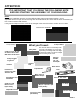
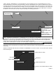
STEP 2: BASE RAIL ASSEMBLY
Place the starter base rails in the front corners of the building 1 1/2” in from the sheeting ledge on the sides of the slab.
(See FRONT DETAIL below) The outside dimension of the base rails should be your building width (12’, 20’, 24’, or 30’)
The starter base rails are ether 6’-2”, 8’-2” or 10’-2” long with 2 or 3 welded vertical pins. The 8’-2” rails are for 4’ on cen-
ter frames and the 10’-2” rails are for 5’ on center frames and the 6’-2” rails are for 6’ on center frames.
Now, insert 8’ or 10’ length extension base rails into the starter base rails as shown until you get to the desired building
length. NOTE: the last base rails that you insert to get to your building length may be 4’ or 5’ base extensions.
The vertical pins should be on 4’ or 5’ centers. Measure the distance from the end pin on each base rail to the first pin on
the next inserted base rail and adjust the joint so that all the pins are on 4’ or 5’ centers. (46” or 58” between pins)
HINT: IT may be helpful to cut a spacer board 46” or 58” to use as a guide for pin spacing. When you are sure that you
have all the base rails in the proper location, fasten each joint with two #12 self-drilling screws on the top of the base rail.
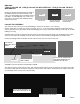
ANCHORING THE BASE RAILS:
Check with your local building official to see if concrete expan-
sion bolts are acceptable in your area. Some regions may
require adhesive anchors. We recommend 1/2” x 7” expansion
anchors with a 1/2” flat washer.
INSTALLATION:
Use a 1/2” concrete bit in a hammer drill to drill a 5” deep hole in
the slab. Use the anchor hole in the tube as a guide. Place the
washer and nut on the top of the bolt with about 2 threads
showing. Tap the bolt into the hole with a hammer and tighten
the nut until it is good and snug. Do not crush the base rail tube.
PIN
4’ OR 5’
4’ OR 5’
STARTER BASE RAIL
8’-2” OR 10’-2” (3) PINS
EXTENSION BASE RAIL
8’-2” OR 10’-2” (2) PINS.
(AS MANY AS NEEDED TO
GET TO YOUR BUILDING
LENGTH
EXTENSION BASE RAIL
4’ OR 5’
ACTUAL SIZES:
52 3/4”, (1) SWAGE, (1)
PIN OR
64 3/4”, (1) SWAGE, (1)
PIN.
SOME BUILDINGS WILL
NOT HAVE A 4’ OR 5’
EXTENSION AT THE
END
1 1/2”
1 1/2”
1 1/2”
FRONT VIEW
1 1/2”
1 1/2”
SIDE VIEW
JOINT DETAIL
7”
PLACE THE END OF THE
STARTER RAIL WITH 2 ANCHOR
HOLES IN THE CORNER OF THE
BUILDING
LAYOUT FOR 6’ ON CENTER BASE RAILS
6’ STARTER RAIL 6’ BASE EXTENSION