
Specifications


DMU-2000 DATA MANAGEMENT UNITPage 2
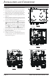
1. Make certain that all cables are disconnected from the
transceiver.
2. Referring to Figure 1, remove the 18 screws that at-
tach the bottom case, then remove the bottom case.
3. Refer to Figure 2 for the mounting location of the
SCOPE Unit. There is a disconnected 14-pin plug.
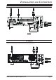
4. Mount the SCOPE Unit using the supplied four screws
(Figure 3).
5. Referring to Figure 3, plug the 14-pin plug which was
removed from the chassis in the previous step into
connector J7002 on the SCOPE Unit.
6. Locate the Coaxial plug
(
labeled
)
installed in jack
(J4006) on the LOCAL Unit. Unplug the Coaxial plug
( )
from the LOCAL Unit and plug it into J7003 on
the SCOPE Unit. Similarly, locate the Coaxial plug
(
labeled
)
installed in jack (J1029) on the MAIN
Unit. Unplug the Coaxial plug
( )
from the MAIN
Unit and plug it into J7003 on the SCOPE Unit.
7. Referring to Figure 4, place the Coaxial cables into
the slots of the chassis.
8. Replace the bottom case and its 18 screws.
9. Assemble the transceiver, Data Management Unit, af-
ter-market Display, and after-market Keyboard (if
used) pursuant to Figure 5.
FIGURE 1
FIGURE 2
SCOPE Unit Mounting Location
14-pin plug
FIGURE 3 FIGURE 4
Move the Coaxial plug
Move the Coaxial plug
Plug the 14-pin plug
Place the Coaxial cables into the slots of the chassis
INSTALLATION AND CONNECTION
FT-950