For Technical Assistance please call our Toll Free 866 number or contact us at the below referenced address. Rugged CCTV TollFree 866-301-CCTV 201 N. Elm St. Phone 903-498-3240 Kemp, TX 75143 Fax 903-498-8989 www.rugged-cctv.
VerteX RTH Series H.8 and H.16 Series FCC Compliance Statement Model Name: H.8 / H.16 and VerteX RTH This device complies with Part 15 of the FCC Rules. Operation is Subject to the following two conductions: (1) this device may not cause harmful interference, and (2) this device must accept any interference received, including interference that may cause undesired operations. WARNING Unauthorized reproduction of all or part of this manual is strictly prohibited.
VerteX RTH Series H.8 and H.16 Series C/O/N/T/E/N/T/S Chapter 1. Introduction.................................................................................................7 1-1. VerteX RTH-Series Major Features........................................................................................................... 7 1-2. H.8 and H.16-Series Major Features........................................................................................................ 8 1-3. About the Product...................
VerteX RTH Series H.8 and H.16 Series 4-10. Recording View ..........................................................................................................................................23 4-11. Backup............................................................................................................................................................23 4-12. DVR Information View ................................................................................................................
VerteX RTH Series H.8 and H.16 Series 5-10-1. Playback and Playback Speed Control ................................................................................................ 33 5-10-2. Smart Search.................................................................................................................................................. 34 5-10-3. Calendar Search ......................................................................................................................................
VerteX RTH Series H.8 and H.16 Series 6-4. Storage .............................................................................................................................................................51 6-4-1. Private Recording............................................................................................................................................ 52 6-4-2. HDD Overwrite...............................................................................................................
VerteX RTH Series H.8 and H.16 Series [Figure 2-2. H.8 AND H.16-16 Basic Connection and Device Connection]........................................................12 [Figure 2-3. Terminal Block TB1].........................................................................................................................................13 [Figure 2-4. Terminal Block TB1 Description].................................................................................................................14 [Figure 4-5.
VerteX RTH Series H.8 and H.16 Series [Figure 5-45. Tour Setup Window]......................................................................................................................................57 [Figure 5-46. Setup Network Window] ..............................................................................................................................57 [Figure 5-47. DDNS Window] ...............................................................................................................
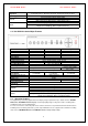
VerteX RTH Series System Operation & Adjustment System Upgrade Network Others H.8 and H.16 Series Front Button, Mouse, IR Remote Controller, Keyboard Controller, Network USB2.0 Memory Stick, Network System Automation (Controlled by CMS) NTP Supported CMS / Monitoring by Web Browser / PDA / Mobile Viewer 15 Languages Supported, Automatic E-mail Power [12V/5A] / Max. Power Consumption[40W] / Operating Temperature[5-40℃] Weight without HDD[4kg] / Dimension[430*86*270mm] 1-2. H.8 AND H.
VerteX RTH Series H.8 and H.16 Series 1-4. Differences between VERTEX RTH-Series and H.8 AND H.16-Series ITEM DVD Loop Out Spot Out Audio Channel Sensor Channel Relay Channel Remote Controller Front Button USB port Dimension VERTEX RTH-Series OK OK OK 4/2/1 16 / 8 / 4 [1ea NC/NO] [3ea TTL Out] 30 Button(ID not supported) 29 Button Front(right & left) 19’ RACK SIZE H.8 AND H.16-Series NO NO NO 1/1/1 4/4/4 [1ea NC/NO] 14 Button(ID supported) 14 Button Right Rear side COMPACT SIZE 1-5.
VerteX RTH Series H.8 and H.16 Series 2-1-3. VERTEX RTH-Series 8 Channel Rear Part 2-1-4. VERTEX RTH-Series 16 Channel Rear Part No.
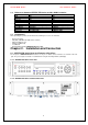
VerteX RTH Series H.8 and H.16 Series 2-2-2. Not currently offered 2-2-3. H.8 Rear Panel 2-2-4. H.16 Rear Panel No.
VerteX RTH Series H.8 and H.16 Series 2-3. Installation and Connection [Figure 2-1. VERTEX RTH-16 Basic Connection and Device Connection] [Figure 2-2. H.16 Basic Connection and Device Connection] 2-3-1. Basic Connection By referring to above [Figure 2-1. VERTEX RTH-16 Basic Connection and Device Connection] and [Figure 2-2. H.16 Basic Connection and Device Connection], Connect the CCTV camera, CCTV monitor (or VGA monitor), and USB mouse to the DVR and set up CONFIG SWITCH.
VerteX RTH Series H.8 and H.16 Series 1. The input video type must be either NTSC or PAL; these two types must not be used together. 2. Select the input video format (NTSC/PAL) using the CONFIG switch on the rear side of the product. 3. Select the output monitor type (VGA/TV) using the CONFIG switch on the rear side of the product. 4. CONFIG SWITCH 1) VGA Mode Resolution of VGA Monitor is SXGA (1280*1024) and CCTV Monitor output is not supported.
VerteX RTH Series H.8 and H.16 Series [Figure 2-4. Terminal Block TB1 Description] Terminal Blocks in the rear of the product are for connections of RS-232 / PTZ / Sensor / Relay / TTL Connection. Terminal Blocks may not be available depending on the model. 4) PTZ Camera Connect PTZ control cable; TRX+, TRX- and GND to Terminal Block(TB1);No.4 TRXD+, No.5 TRXD- and No.10 GND in the rear of DVR. PTZ Camera may not be working properly if GND is not connected.
VerteX RTH Series H.8 and H.16 Series 3-1. VERTEX RTH-Series Front Button No.
VerteX RTH Series H.8 and H.16 Series 3-2. VERTEX RTH-Series Remote Controller A, Basic Control Button POWER RECORD ~ Turns the system power ON or OFF Records all channels or stops recording all channels NUMBER Enables input of numeric data ID Sets up the remote controller ID B.
VerteX RTH Series H.8 and H.16 Series ※ Setting up the remote controller ID Example) When the remote controller ID is set to 1 Press the [ID] button, enter a two-digit remote controller ID, and press the [ID] button again. , , To control all DVRs with different IDs, set the remote controller ID to 999. 3-3. H.8 AND H.16-Series Front Button No.
VerteX RTH Series H.8 and H.16 Series 3-4. Remote Controller for H.8 AND H.16-Series A. B. Basic Control Button POWER System Power ON / OFF ESC Exits the current Menu Or selects the upper menu MENU Data, Schedule, System setup MODE Screen Mode Menu SELECT Selects the category or automatic screen conversion MOVE Moves from one category to another or changes the display mode executes Search Button (Playback Mode) Reverse Play Play Reverse Frame by Frame Pause Frame by Frame 3-5.
VerteX RTH Series H.8 and H.16 Series Chapter 4. DVR Operation Setup 4-1. VERTEX RTH-Series Storage Installation ※ Recommended HDD Specification Type Size Capacity Buffer RPM SATA I, II 3.5 1, 2 Flat Up to 1.5TB over 8MB over 7200 1) Using a screw driver, unscrew and take off the top case of the product. 1) Normal termination of the system and fully unplugged power code are required before conducting HDD installation.
VerteX RTH Series H.8 and H.16 Series 4-2. H.8 AND H.16-Series Storage Installation ※ Recommended HDD Specification Type Size Capacity Buffer RPM SATA I, II 3.5 1, 2 Flat Up to 1.5TB over 8MB over 7200 1) Using a screw driver, unscrew and take off the top case of the product. 1) Normal termination of the system and fully unplugged power code are required before conducting HDD installation.
VerteX RTH Series H.8 and H.16 Series 7) Reassemble the top case by reversing 1) to finalizing HDD installation. 4-3. Power ON. Check the adapter (12VDC/3.5A) and connect the power. Booting will be initiated by pressing the power button in the front panel. Booting is progressed step by step by VGA outputting or a color bar test screen for TV outputting, Live screen and a clock. Menu widow pops up by clicking the right button of the mouse or pressing [MENU] button in the front panel as shown below.
VerteX RTH Series H.8 and H.16 Series [Figure 4-7. Storage Device New Tab Window] Direct Initialize Backup Initialize Changes the selected storage into a dedicated direct storage. Changes the selected storage into a backup storage. {New} At least, one storage shall be selected as a dedicated storage. Otherwise, the data cannot be stored in real time. ④ Select {Direct-Init} and follow {Direct-Init} procedure. {Direct-Init} procedure may take time.
VerteX RTH Series H.8 and H.16 Series 4-6. Date/Time Setup Select {Menu} Æ {Setup} Æ {Time}. Set up [Time Sever]/[Date and Time]/[Standard Time Zone] 4-7. Camera / TV Setup Select {Menu} Æ {Miscellaneous} Æ {Camera/TV Setting}. Set up for [Brightness/Contrast/Color/Hue/Camera Adjustment/TV OUT Adjustment] are available. 4-8. Screen View Setup and Others Setup Select and set up {Menu} Æ {Miscellaneous} Æ {Display Mode}. Select and set up {Menu} Æ {Miscellaneous} Æ {Display Setting}.
VerteX RTH Series H.8 and H.16 Series Chapter 5. System Operation 5-1. Starting and Exiting the System 5-1-1. Starting the System With the power connected, press the Power button. After the system is booted, images of all connected channels will be displayed. 5-1-2. Exiting the System ※ The default password for the local administrator is “00000.” ※ To change the password, select {Main Setup} Æ {System} Æ {Local Administrator’s Password}. Press the Power button on the remote controller.
VerteX RTH Series H.8 and H.16 Series ※ The user can view an image on full screen by double-clicking the 4/9/16 Sub-Screen mode. Double-click any part of the screen to return to the previous mode. ※ Auto Sequence Auto Sequence is to rotate images at an interval of the certain time in 1/4/9 Sub-Screen Mode. It changes to Auto Sequence Mode if you select {Menu} Æ {Miscellaneous} Æ {Display Mode}Æ{Sequence} in 1/4/9 Sub-Screen Mode.
VerteX RTH Series H.8 and H.
VerteX RTH Series H.8 and H.16 Series [Figure 4-10. Recording Status Window] ※ Functions available for Authorization Setup Video is not connected or Video is covert. Audio is set activated. Audio is set silent. Channel Title Channel title Time Current time Green Recording Mode No Signal Continuous Recording Red Motion Recording Blue Sensor Recording Camera has been disconnected. 5-5-1. System Information On the real-time monitoring screen, select {Menu} Æ {Miscellaneous}Æ{DVR Info.}.
VerteX RTH Series H.8 and H.16 Series [Figure 4-11. Product Information Window] ID is an identification(1~99, 255) of the product. The remote controller ID must match the identification to control DVR system. 5-5-2. Camera Selection for Screen Setup On the real-time monitoring screen, select {Menu} Æ {Miscellaneous} Æ {Camera/TV Setting}. Select a camera for Screen Setup. If you tick on All Channels, you can set up screen over all channels. [Figure 4-12. Camera/TV Setup Window] 5-5-3.
VerteX RTH Series H.8 and H.16 Series On the real-time monitoring screen, select {Menu} Æ {Miscellaneous} Æ {Camera/TV Setting} Æ{Camera Adjustment}. Select a camera to be adjusted. Adjust the position of the selected camera using the arrow keys. Adjust the other camera by repeating ② and ③ Moving the camera, down, right, or left excessively may cause black or gray areas to appear on the screen. The level at which such condition does not occur is the proper control range for the camera. 5-5-5.
VerteX RTH Series H.8 and H.16 Series 5-6. Spot Control (Only for VERTEX RTH series) [Figure 4-14. Spot Control Window] On the real-time monitoring screen, select {Menu} Æ {Miscellaneous} Æ {Misc. Control} Æ {Spot}. Select a channel or Sequence, and then the selected channel screen will be displayed. 5-7. Relay Out [Figure 4-15. Relay Control Window] On the real-time monitoring screen, select {Menu} Æ {Miscellaneous} Æ {Misc.
VerteX RTH Series H.8 and H.16 Series The user can play back from the last played time by Multi-Channel Mode. ※ Go To The First and Go To The Last are only available in {Multi-Channel} 5-9. Calendar Search 5-9-1. Search Mode On the real-time monitoring screen, select {Menu} Æ {Search} Æ {Calendar Search} and then a searching window pops up as shown below. [Figure 4-17. Search Window] 5-9-2. Year/Month/Day Selection Select the desired [Year/Month/Day].
VerteX RTH Series H.8 and H.16 Series Green Continuous recording is in progress. Red Motion recording is in progress. Blue Sensor recording is in progress. Sky-Blue A image that recorded before the time change Move the time line to a specific time point using the arrow keys or the numeric buttons and press the Search button. Selecting the time causes the recorded video for each channel to be displayed as a bar graph in minute units.
VerteX RTH Series H.8 and H.16 Series [Figure 4-18. Playback Screen] 5-10-1. Playback and Playback Speed Control In Playback mode, the user can play back video contents using the button functions below. After the data is played to the end, the data of the next time zone will be automatically searched and played (this function is possible only in Multi-channel Playback mode; both backward playback and forward playback are possible).
VerteX RTH Series H.8 and H.16 Series Status bar indicating information of the hourly recorded image data. Selecting the right-mouse button or menu button in Playback Mode pops up the {Playback Menu} Items in {Playback Menu} is shown below. [Figure 4-20. Playback Menu] 5-10-2. Smart Search This function is used to search an image with the object movement at a specific zone fast. Searching by each channel is available. Move to Smart Search and select the desired channel.
VerteX RTH Series H.8 and H.16 Series 5-10-9. Display Mode The user can divide the screen in Playback Mode as same as in Monitoring Mode. Select Screen Mode and Screen Mode window as shown below pops up. [Figure 4-22. Display Mode] Select [1/4/9/16 Mode] 5-10-10. Status Bar Select Activation or Deactivation below Playback Mode [Figure 4-19. Playback Status and Control Window]. 5-11.
VerteX RTH Series H.8 and H.16 Series Select button. The user can check the time and the log type using the arrow keys in the log list. Use the Up/Down button to check the logs by time and type on each page. The user can shift the focus to a certain time zone for playing the certain time (playback will start from the time point when logs are saved). Click the right-mouse button or select {Menu} button in the front panel and select {Hour} to move the desired log time zone. [Figure 4-24.
VerteX RTH Series H.8 and H.16 Series 5-12-3. Recording Status View A. Recording Status by Color B. Green Continuous recording is in progress. Red Motion recording is in progress. Blue Sensor recording is in progress. Starting and Stopping Record All In real-time monitoring mode, the user can start or stop the recording of all channels by selecting {Menu} Æ {Miscellaneous} Æ {Record On/Off} C.
VerteX RTH Series H.8 and H.16 Series screen mode, however, only those channels that can be viewed may be selected. For the remaining backup procedures, see {4-13-5 Common Backup Procedure}. 5-13-5. Common Backup Procedure [Figure 4-25. Backup Window] [Figure 4-25] shows the initial backup window menus. A list of devices that can be selected as well as simple information on the currently selected devices are outputted.
VerteX RTH Series H.8 and H.16 Series If the backup storage device is not formatted, in case the box displaying the size of the file to be backed up is displayed in yellow, and if backup is executed by pressing the Copy (Backup) button, a prompt asking whether to erase the device will appear as shown below. Selecting [YES] causes the storage medium for the selected device to be erased. Press the Copy (Backup) button. A prompt asking whether to proceed with the backup or not will then be displayed.
VerteX RTH Series H.8 and H.16 Series 5-15-2. PTZ Mode In real-time monitoring mode, select {Menu} Æ {PTZ Control}. PTZ Control Window shows up. PTZ Control Window can be toggled as {Max.} or {Min.} as shown below. [Figure 4-26. PTZ Control Window (Max. Mode (Left) / Min. Mode (Right) )] A channel with PTZ set camera is activated in the yellow frame. [Figure 4-27. PTZ Mode Initial Screen] Activation mode The channel is selected, and the channel screen border is highlighted in orange. 5-15-3.
VerteX RTH Series H.8 and H.16 Series ※ For more information on setting the Tour feature, select {Menu} Æ {Setup} Æ {PTZ} Æ {Tour}. In Tour, you can select [Disable] / [Able]. If you choose [Able], [Tour 1] and [Tour 2] are available. 8 spots of PTZ preset are available for each [Tour1] and [Tour2]. In Tour {Menu} Æ {PTZ Control}, you can set up Tour1/Tour2 and [Disable]. D. horizontal/vertical Control horizontal/vertical movement using the arrow keys. E.
VerteX RTH Series H.8 and H.16 Series the user, and the related log, saved. If synchronization with the NTP server fails, synchronization with RTC will be established. 2) Synchronization with the DVR Time Server The DTS server is executed in the VERTEX RTH, H.8 AND H.16-series; time is synchronized every hour. VERTEX RTH, H.8 AND H.16 series DTS clients referring to the DTS synchronize the time of the DVR system operating with DTS.
VerteX RTH Series H.8 and H.16 Series 6-1-2. Date and Time [Figure 5-29. Date and Time] A. Date and Time Only available when Time Server is off The system date and time format is Year/Month/Day Hour/Minute/Second. Using the arrow keys and the Select button, move the focus onto the desired field; Year/Month/Day Hour/Minute/Second and press the Select button. Select the field you want to change using the arrow buttons and press the [Select] button. B.
VerteX RTH Series C. H.8 and H.16 Series Start Time Using the arrow keys and the Select button, select {Start Time}. On the selection window, set up Start Time using the arrow keys and the Select button. D. End Time Using the arrow keys and the Select button, select {End Time}. On the selection window, set up End Time using the arrow keys and the Select button. ※ For a weekly setting in the {Start Time} and {End Time} fields, set Day to 0.
VerteX RTH Series H.8 and H.16 Series [Figure 5-32 Letter Input Window] B. Covert Used to hide the video channel on the real-time monitoring screen. ※ Video data are saved on the real-time monitoring screen even though they are not displayed in black. C. Connection Used to set whether to connect or disconnect each camera channel. ※ When the camera channel is set to disconnected, the video contents will not be displayed even if the camera is actually connected.
VerteX RTH Series H.8 and H.16 Series Recording Type Continuous Setting {Record} Æ {Rate} Æ Normal: 1~30 Motion {Event} Æ {Motion}: Part or All Sensor {Event} Æ {Sensor}: 1~16 Automatic {Record}Æ{Rate}Æ Event: 1~30 Enables setting both Normal and Event simultaneously E) Recording Frame In case of Continuous/Motion/Sensor/Audio Mode, the user can only set the frame. In case of Automatic Mode, the recording frame can be divided into the {Normal} type and {Event} type.
VerteX RTH Series A. H.8 and H.16 Series All Detect all movements of images in each channel. Record only for the time set at {Recording} Æ {Event} Æ {Post-Event} Select the channel to be set up at {Recording} Æ {Event} Æ {Motion Detection} using the arrow keys and the Select button. Select {All} on the selection window. B. Partial Detect movements of images on a certain designated area in each channel. Record only for the time set at {Recording} Æ {Event} Æ {Post-Event}.
VerteX RTH Series H.8 and H.16 Series sensors can be set. When a signal of an external sensor is detected, the video of the corresponding channel will be recorded. In the sensor selection window, select a external sensor channel. Select the sensor type. NC(Normal Close) : Normally closed; opens when a signal is received NO(Normal Open) : Normally open; closes when a signal is received C) Post-Event Set up the time of the recording duration after an event is taken place. Select between 5 – 300 seconds.
VerteX RTH Series H.8 and H.16 Series Select the channel at {Menu} Æ {Setup} Æ {Recording} Æ {Alarm Action} Æ {PTZ Preset}. Select {Preset Action}. [Figure 5-36. Preset Action Setup Window] The user can set every channel with the same duration by pressing the Select button after moving the focus on the top of {Preset} column. Preset are available up to 1 ~ 8. C) E-mail When an alarm or an event occurs, emails will be sent to the specified email address.
VerteX RTH Series H.8 and H.16 Series 6-3. Recording Schedule {Recording Schedule} is used to save the system configuration as data from Data 1 to Data 4 and to make a recording based on the system configuration for each day/time zone. [Figure 5-37. Recording Schedule Window] 6-3-1. Enter to Recording Schedule Menu Select {Menu} Æ {Setup} Æ {Recording Schedule}. Recording Schedule Window appears as shown in [Figure 5-37]. 6-3-2.
VerteX RTH Series H.8 and H.16 Series [Figure 5-38. Holiday Registration Window] If the date for the holiday and day of the week are the same in the {Recording Schedule} menu, the holiday setup will have priority over the date setup. Ⓐ Calendar The defined holidays will be indicated with a red tag. Ⓑ Holiday List The list of all defined holidays will be displayed. A total of 15 holidays will be displayed per page, and the rest, on the succeeding pages.
VerteX RTH Series H.8 and H.16 Series [Figure 5-39. Storage Window (Local)] To apply the new setting, save the new setting. Initialization: initialize the menu as the basic setting. Save: Saves the setting data. Exit: Ask if the user wants to save the setting data. 6-4-1. Private Recording This is to limit the recording days. If you set it as 30days, max. 30days will be recorded and over 30days recording data will be automatically deleted. 6-4-2. HDD Overwrite Set On/Off for HDD Overwrite.
VerteX RTH Series H.8 and H.16 Series real time. Five commands can be executed. Depending on the S/W status, however, some commands cannot be executed. New Returns the status of the selected storage device to New; if this command is executed, the selected storage device will be moved to the {New} storage device manager. Online Changes the selected storage device in online state. Offline Changes the selected storage device in offline state. Format Format the selected storage.
VerteX RTH Series H.8 and H.16 Series Open the system body and install a new disk (connect the data cable and the power cable). Connect power to the system and boot the system. Select {Menu} Æ {Setup} Æ {Storage} using the arrow keys and the Select button. A newly displayed disk will then be displayed as {New}. Select a newly installed disk using the arrow keys and the Select button and initialize the disk as a {Direct} or a {Backup} disk. The following describes the method of setting a direct storage.
VerteX RTH Series H.8 and H.16 Series [Figure 5-41. Storage Format] Then, the user is able to choose [New/Online/Format/Eject]. Select Format and formatting progress as shown below. [Figure 5-42. Storage formatting in progress message] It may take time during formatting. After formatting, select the model again and set as Online. Format is completed. 6-5. PTZ Set the PTZ camera connected to the system. {Menu} Æ {Setup} Æ {PTZ}. [Figure 5-43.
VerteX RTH Series H.8 and H.16 Series From the PTZ Setup menu, select the PTZ protocol for the channel you want to set using the arrow keys and the Select button. [Figure 5-44. PTZ Protocol Window] On the selection window, select the PTZ protocol using the arrow keys and the Select button. 6-5-2. Camera ID setup Camera ID refers to the address used for communicating with the PTZ camera. ※ The camera ID must be the same as the ID set in the PTZ camera.
VerteX RTH Series H.8 and H.16 Series Select Tour of the desired channel. Two Tour are available in VERTEX RTH, H.8 AND H.16 series and each Tour can be set with eight presets. [Figure 5-45. Tour Setup Window] Set Tour in the selection window. 6-6. Network Set the system network. {Menu} Æ {Setup} Æ {Network} 6-6-1. Ethernet 1) TCP/IP Setup is performed to use a fixed IP in the local area network environment. [Figure 5-46. Setup Network Window] Select {Ethernet} in {Menu} Æ {Setup} Æ {Network}.
VerteX RTH Series H.8 and H.16 Series 6-6-2. DDNS As part of the DNS system, the Dynamic Domain Name System (DDNS) service updates the IP addresses of host names in real time and allocates fixed domain names to systems linked to dynamic IP addresses to allow users to use the same DNS name regardless of the changes in the IP address. The VERTEX RTH, H.8 AND H.16 series provides dynamic DNS to ensure URL access in the dynamic IP environment.
VerteX RTH Series H.8 and H.16 Series [Figure 5- 48. DDNS Window with MAC Address] [Figure 5- 49. DDNS Setting] [Figure 5-50.
VerteX RTH Series H.8 and H.16 Series [Figure 5-51. DDNS Status] Select {DDNS} in {Menu} Æ {Setup} Æ {Network}. Save after entering the DDNS Enable as ‘cctvuser On’ as Figure 5-47. MAC address is automatically saved as DDNS address as Figure 5-48. You can see the sign ‘ Wait please…Loading as Figure 5-49. After that, it is working fine if every network setup is correct. If you are not familiar with MAC Address as a DDNS, you can change it whatever you like.
VerteX RTH Series H.8 and H.16 Series [Figure 5-52. Port Window] Select {Port} in {Menu} Æ {Setup} Æ {Network}. Save after entering each port number. 6-6-4. E-mail Automatic E-mail transmission service when an alarm or an event occurs. To use the e-mail function, {E-mail} in {Menu} Æ {Setup} Æ {System} Æ {9. Alarm} needs to be configured. [Figure 5-53. E-mail Window] Select {Menu} Æ {Setup} Æ {Network} Æ {E-mail}. Save after entering the detail about E-mail. 6-7.
VerteX RTH Series H.8 and H.16 Series 8. RS232C Port 9. Error Alarm Action 10. Error Alarm Duration Use of the RS232C port Set the alarm On/Off and alarm format. Set the alarm time by continuous/5/10/15/User Setup. Used to set the time for exiting the System Setup menu automatically and displaying the real-time monitoring screen. System OSD language setting 11. Menu Time Out 12. Language 6-7-1. System Menu Select System at {Menu} Æ {Setup}. System Setup Window, as shown below, appears.
VerteX RTH Series H.8 and H.16 Series Move to {Menu} Æ {Setup} Æ {System} Æ {2. Remote Controller ID}. In the selection window, enter ID using the arrow keys and the Select button (the number 0~99 is available for ID.) If you forgot the DVR ID, set the remote controller ID to 999 to start the DVR. Note, however, that the DVR ID should be the same as the remote controller ID. ※To Configure Remote Controller ID (Example: ID setting as 3) 1) Press {ID} button on the remote controller.
VerteX RTH Series H.8 and H.16 Series [Figure 5-55. User Authorization Setup Window] (2) Add Users Move to {Menu} Æ {Setup} Æ {System} Æ {Users} Æ {User Addition}. On the user registration window, enter the ID and the password. Up to four users can be registered (the user ID and password may contain up to 30 English letters) After entering the user ID and password, select the user authorization. (3) Delete Users Move to {Menu} Æ {Setup} Æ {System} Æ {Users} Æ {User Delete}.
VerteX RTH Series H.8 and H.16 Series [Figure 5-57. Firmware Upgrade Progressing Window] ※ Downgrading to a previous version is not supported. ※ It is recommended that the DVR ID should be the same as the remote controller ID. ※ The upgrade information window will then appear within 15 seconds. Read the information and select {Yes} to start the upgrade gradually. Select {No} to return to {System} mode. After the update is completed, the system will be rebooted. The system will automatically start.
VerteX RTH Series H.8 and H.16 Series E-mail / Relay Device / System Check] 6-7-11. Error Alarm Duration Events and others Move to {Menu} Æ {Setup} Æ {System} Æ {10. Error Alarm Duration}. In the selection window, set Alarm out time using the arrow keys and the Select button. 6-7-12. Menu Time Out If no input is made in the System Setup menu using the front buttons, remote controller, or mouse, the system automatically shifts to real-time monitoring mode. Move to {Menu} Æ {Setup} Æ {System} Æ {11.
VerteX RTH Series H.8 and H.16 Series 1) Recommended HDD Specification Type Size Capacity Buffer RPM SATA I, II 3.5 1, 2 Flat Up to 1.5TB over 8MB over 7200 2) Recommended PTZ Camera Protocol NO Vendor Model ULTRA_7 Protocol 1 A.D.