
Service manual


13
Alignment
Introduction
The VX-160/-180 has been aligned at the factory for
the specified performance across the entire frequency range
specified. Realignment should therefore not be necessary
except in the event of a component failure. All component
replacement and service should be performed only by an
authorized Vertex Standard representative, or the warranty
policy may be voided.
The following procedures cover the sometimes critical
and tedious adjustments that are not normally required once
the transceiver has left the factory. However, if damage
occurs and some parts are replaced, realignment may be
required. If a sudden problem occurs during normal op-
eration, it is likely due to component failure; realignment
should not be done until after the faulty component has
been replaced.
We recommend that servicing be performed only by
authorized Vertex Standard service technicians who are
experienced with the circuitry and fully equipped for re-
pair and alignment. Therefore, if a fault is suspected, con-
tact the dealer from whom the transceiver was purchased
for instructions regarding repair. Authorized Vertex Stan-
dard service technicians realign all circuits and make com-
plete performance checks to ensure compliance with fac-
tory specifications after replacing any faulty components.
Those who do undertake any of the following alignments
are cautioned to proceed at their own risk. Problems caused
by unauthorized attempts at realignment are not covered
by the warranty policy. Also, Vertex Standard must re-
serve the right to change circuits and alignment proce-
dures in the interest of improved performance, without
notifying owners. Under no circumstances should any
alignment be attempted unless the normal function and
operation of the transceiver are clearly understood, the
cause of the malfunction has been clearly pinpointed and
any faulty components replaced, and the need for realign-
ment determined to be absolutely necessary. The follow-
ing test equipment (and thorough familiarity with its cor-
rect use) is necessary for complete realignment. Correc-
tion of problems caused by misalignment resulting from
use of improper test equipment is not covered under the
warranty policy. While most steps do not require all of the
equipment listed, the interactions of some adjustments may
require that more complex adjustments be performed af-
terwards. Do not attempt to perform only a single step
unless it is clearly isolated electrically from all other steps.
Have all test equipment ready before beginning, and fol-
low all of the steps in a section in the order presented.
Required Test Equipment
U Avionics Radio Tester with calibrated output level at
500 MHz
U In-line Wattmeter with 5% accuracy at 500 MHz
U 50-ohm, 10-W RF Dummy Load
U Regulated DC Power Supply (standard 7.5V DC, 2A)
U Frequency Counter: ±0.2 ppm accuracy at 500 MHz
U AF Signal Generator
U AC Voltmeter
U DC Voltmeter
U UHF Sampling Coupler
U IBM PC/compatible Computer with Microsoft DOS
v3.0 or later operating system
U Vertex Standard CT-42 Connection Cable and CE44
Alignment program
Alignment Preparation & Precautions
A 50-ohm RF Dummy load and in-line wattmeter must
be connected to the main antenna jack in all procedures
that call for transmission, except where specified other-
wise. Correct alignment is not possible with an antenna.
After completing one step, read the following step to
determine whether the same test equipment will be re-
quired. If not, remove the test equipment (except dummy
load and wattmeter, if connected) before proceeding.
Correct alignment requires that the ambient tempera-
ture be the same as that of the transceiver and test equip-
ment, and that this temperature be held constant between
20° and 30°C (68°~ 86°F). When the transceiver is brought
into the shop from hot or cold air, it should be allowed
time to come to room temperature before alignment.
Whenever possible, alignments should be made with
oscillator shields and circuit boards firmly affixed in place.
Also, the test equipment must be thoroughly warmed up
before beginning.
Note:Signal levels in dB referred to in this procedure are
based on 0 dBµ = 0.5 µV (closed circuit).
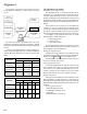
Important Note
When connecting the CT-42 plug into the MIC/SP
jack of the VX-160/-180, you must remove the plas-
tic cap and its mounting screws prior to programming.
Please remember to re-attach the cap and screws when
the programming is complete.