
Service manual


14
Alignment
The transceiver must be programmed for use in the
intended system before alignment is attempted. The RF
parameters are loaded from the file during the alignment
process.
In order to facilitate alignment over the complete op-
erating rang of the equipment, it is recommended that the
channel data in the transceiver be preset as per the chart
below.
Channels
Frequency (MHz)
Ver. A Ver. C Ver. CS1
Low Band Edge 134.000 146.000 142.000
(Channel 1) (Low POWER) (Low POWER) (Low POWER)
Band Center 147.000 160.000 159.000
(Channel 2) (High POWER) (High POWER) (High POWER)
High Band Edge 160.000 174.000 176.000
(Channel 3) (High POWER) (High POWER) (High POWER)
Tone-Frequency (Hz) / DCS-code
Channel
Ver. A Ver. C Ver. CS1
CTCSS
DCS
CTCSS
DCS
CTCSS
DCS
Low Band Edge
––––––
(Channel 1)
Band Center
151.4 – 151.4 – 151.4 –
(Channel 2)
High Band Edge
– 627 – 627 – 627
(Channel 3)
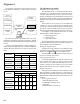
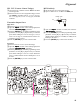
Set up the test equipment as shown below for trans-
ceiver alignment, and apply 7.5V DC power to the trans-
ceiver.
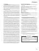
The alignment tool outline
Installation of the Alignment tool
The “alignment mode” is a software-based protocol,
accessed by an “Alignment Mode” command from the
computer while switching the transceiver on.It is oper-
ated by the alignment tool automatically. During use of
the alignment mode, normal operation is suspended. The
alignment tool program provides all needed operation ca-
pability.
The alignment tool consists of an executable file
“CE44.exe” and an accmpanying configuration file
“CE44.cfg” which should be loaded per standard DOS
procedures. Create a suitable directory, then copy these
foles from the distribution diskette into the new directory.
For example, if copying the file from Drive A, use the
following DOS command sequence:
c:\ mkdir align [enter]
c:\ cd align [enter]
c:\ align\ copy a:ce44.*
No further installation steps are required. If you wish
to utilize a different name for the alignment directory, it
will not matter to the executable file.
Booting the Alignment Tool
Change to the “align” directory (or the directory name
you utilized in the previous section). Now type on the com-
mand line: ce44
ENTER to boot the alignment tool.
The introductory screen will appear, and you may press
any key to enter the main screen.
Entering Alignment Mode
To enter the alignment mode, turn the transceiver off,
Select “Radio” then “Adjust ” parameter. Now, turn the
transceiver back on. When the command has been suc-
cessful, a message on the computer screen will confirm
that the transceiver is now in the “Alignment” mode.
Alignment Sequence
Although the data displayed on the computer's screen
during alignment is temporary data, it is important you
follow the basic alignment sequence precisely, so that the
displayed data and the data loaded into the transceiver are
identical.
Basic Alignment Sequence
1. Enter the alignment mode
2. Upload data from transceiver
3. Align data
4. Download data to transceiver
50-ohm
Dummy Load
Inline Wattmeter
Deviation Meter
Frequency
Counter
RF Sampling
Coupler
RF Signal
Generator
Transceiver
Power Supply
7.5V DC
CT-42 connection
Cable
PC
MIC/SP
COM port