
Service manual


15
PLL VCV (Varactor Control Voltage)
U Connect the DC voltmeter between TP3 on the Main
Unit and ground.
U Set the transceiver to CH 3 (high band edge), and ad-
just L1004 on the Main Unit for 3.7~3.8 V (Typ C),
3.0~3.1 V (Typ CS1) or 3.4~3.5 V (Typ A) on the DC
voltmeter.
Transmitter Output Power
High Power
U Set the transceiver to CH 2 (band center).
U Open the “
AdjustAdjust
AdjustAdjust
Adjust” window on the CE44 program, then
select the “
RF Power (High)RF Power (High)
RF Power (High)RF Power (High)
RF Power (High)” parameter.
U Press the
[
ENTER
]
key to enable programming of this
parameter; use the
[
]
or
[
]
arrow keys so that the
power meter reading is 5.5 W ± 0.1 W (Typ C, CS1) or
5.0 W ± 0.1 W (Typ A). Confirm that the current con-
sumption is 2.2 A or lower.
U Press the
[
ENTER
]
key to lock in the new data.
Low Power
U Set the transceiver to CH 1 (Low band edge).
U Open the “
AdjustAdjust
AdjustAdjust
Adjust” window on the CE44 program, then
select the “
RF Power (Low)RF Power (Low)
RF Power (Low)RF Power (Low)
RF Power (Low)” parameter.
U Press the
[
ENTER
]
key to enable programming of this
parameter; use the
[
]
or
[
]
arrow keys so that the
power meter reading is 1.0 W ± 0.1 W (for “RF Power
Low”). Confirm that the current consumption is 1.0 A
or lower.
U Press the
[
ENTER
]
key to lock in the new data.
MIC Sensitivity
U Set the transceiver to CH 2 (band center).
U Inject a 1 kHz tone at –37 dBm to the MIC jack.
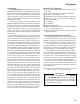
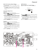
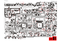
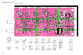
L1004TP3
U Open the “
AdjustAdjust
AdjustAdjust
Adjust” window on CE44, then select the
“
MIC SensitivityMIC Sensitivity
MIC SensitivityMIC Sensitivity
MIC Sensitivity” parameter.
U Press the
[
ENTER
]
key to enable programming of this
parameter; use the
[
]
or
[
]
arrow keys so that the
deviation meter reading is ±3.0 kHz (±0.1 kHz) (for 25
kHz steps) deviation.
U Press the
[
ENTER
]
key to lock in the new data.
SP
CLONE GND
IN
Alignment