VX-1700 Operating Manual VERTEX STANDARD CO., LTD. 4-8-8 Nakameguro, Meguro-Ku, Tokyo 153-8644, Japan VERTEX STANDARD US Headquarters 10900 Walker Street, Cypress, CA 90630, U.S.A. YAESU EUROPE B.V. P.O. Box 75525, 1118 ZN Schiphol, The Netherlands YAESU UK LTD. Unit 12, Sun Valley Business Park, Winnall Close Winchester, Hampshire, SO23 0LB, U.K. VERTEX STANDARD HK LTD. Unit 5, 20/F.
Table of Contents General ......................................................................... 1 Front Panel Control & Switches ................................ 2 Rear Panel Connections .............................................. 4 Installation .................................................................... 5 Safety Precautions ................................................... 5 Power Connections .................................................. 5 Grounding for Electrical Safety ............
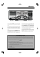
GENERAL The Vertex Standard VX-1700 is a low-cost, integrated HF communications transceiver designed for the Land Mobile market. This advanced transceiver provides 200 memory channels (arranged in five banks) with Alpha-numeric labeling of the memories. And the Selcall feature allows paging of a single transceiver or groups of transceivers by a dispatch center.
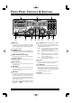
FRONT PANEL CONTROLS & SWITCHES MIC Jack P1 - P4 Keys (PROGRAMMABLE FUNCTION KEYS) This modular jack accepts microphone voice input, as well as scanning and PTT (Push To Talk) control from the microphone. Specified microphone impedance is 500 - 600 Ohms. These four keys functions can be customized, via programming by your Vertex Standard dealer. The factory defaults are shown below.
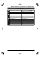
FRONT PANEL CONTROLS & SWITCHES KEYPAD FUNCTIONS Key Secondary Function (Press Primary Function (Press Key) +) None Toggles the IF Bandpass Filter between “WIDE” and “NARROW” in the J2B and A1A modes (only). Toggles the Noise Blanker “on” and “off.” Toggles the Noise Blanker “on” and “off.” Activates the Antenna Tuning process. Activates the Antenna Tuning process on all Memory Channels in the current Memory Bank.
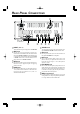
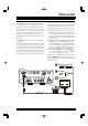
REAR PANEL CONNECTIONS INPUT (13.8 V) TUNER Jack This is the main DC power input jack for the VX-1700. This 8-pin mini-DIN jack is for interconnection to the optional FC-30 or FC-40 External Antenna Tuner. ANT Jack This PL-259 (“M” Type) connector is used for connection of the coaxial feedline from the antenna.
INSTALLATION Safety Precautions Antenna Precautions Before proceeding with installation of the VX-1700 transceiver, please read and observe all safety and operating instructions. Consult with qualified installation or service personnel should any questions arise regarding these important safety tips. Always locate antennas such that they can never come in contact with outdoor power lines in the event of a catastrophic antenna support or power line support structure failure.
INSTALLATION Electromagnetic Compatibility and RF Exposure If this transceiver is used with or in the vicinity of a computer or computer-driven accessories, you may need to experiment with grounding and/or radio frequency interference (RFI) suppression devices (such as ferrite cores) to minimize interference to your communications caused by energy leakage from the computer.
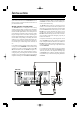
INSTALLATION POWER REQUIREMENTS AND BASIC INSTALLATION DC Power Connections The VX-1700 transceiver is designed for operation from 13.8 Volts DC, negative ground, with the DC source being capable of providing 25 Amperes of continuous current. For mobile applications, the fused (25-A) DC cable supplied with this transceiver may be used for making the power connections.
INSTALLATION MOBILE MOUNTING The optional MMB-89 Mobile Mounting Bracket allows quick insertion and removal of the VX-1700 transceiver from the vehicle. Complete installation instructions are provided with the bracket. vide memory of antenna matching settings sufficient for all channels on Memory Bank 1. In marine applications, the FC-40 is also ideal for the use with a “backstay” antenna or marine mobile whip.
INSTALLATION MOBILE MOUNTING Mobile Station Grounding Although satisfactory grounding in most installations will be achieved via the DC cable’s negative lead and the antenna system’s coaxial cable shield, it may be necessary, in some installations, to provide a direct ground connection at the mounting location of the transceiver. Due to unexpected resonances which may naturally occur in any location, improper communication system performance may result from insufficient grounding.
INSTALLATION BASE STATION INSTALLATION DC Power Connections For base station installations, Yaesu recommends the use of the Model FP-1030A AC Power Supply. The FP1030A provides a regulated 13.8 V DC supply at up to 25 Ampere. Other models of DC power supplies may be used with the VX-1700, but the 13.8 V DC input voltage, 25 Ampere current capability, and DC cable polarity guidelines described previously must be strictly followed.
INSTALLATION BASE STATION INSTALLATION Base Station Antenna Considerations As with mobile or maritime installations, antenna performance is critical to base station communications system effectiveness. Every effort must be made to ensure that the impedance of the antenna system utilized with the VX1700 is as close as practicable to the specified 50-Ohm impedance value, and that mechanical and electrical component integrity are maintained at all times.
INSTALLATION BASE STATION INSTALLATION Excellent reference texts and computer software are available for the design and optimization of HF antennas. Your dealer or installer should be able to assist you with all aspects of your antenna installation. Use high-quality coaxial cable for the lead-in to your VX1700 transceiver. All efforts at providing an efficient antenna system will be wasted if poor quality, lossy coaxial cable is used.
NOTE VX-1700 OPERATING MANUAL Page 13
OPERATION STARTUP PROCEDURES RECEPTION Be certain that all power supply, antenna, ground, microphone, and other accessory connections have been properly accomplished. Rotate the VOL and SQL knobs fully counter-clockwise. Turn on the transceiver by press and holding in the POWER Switch. The LCD display will become illuminated. Rotate the VOL knob for a comfortable listening level on the incoming signals or noise present on the speaker.
OPERATION RECEPTION TRANSMISSION If the station you are listening to should drift or otherwise be unclear (the voice may sound too high-pitched or too low-pitched), pressing the [P1] or [P3] key may improve the sound of the incoming signal. The [P1]/ [P3] key function does not affect your transmission frequency; only the receive frequency is being adjusted. When the receiving frequency is higher than displayed frequency, the “ ” icon will appear to the right of the frequency display.
OPERATION DUAL WATCH The Dual Watch feature allows the user or dispatcher to operate on one channel while periodically making a brief check of Memory Channel “1-001” (Memory Bank #1, Channel #1). The Dual Watch feature can be engaged so long as there is frequency and mode data written into memory channel “1-001.” Every four seconds, the transceiver will automatically switch over to memory channel “1-001.
OPERATION ENCRYPTED TRANSMISSION/RECEPTION (REQUIRES AFTER-MARKET ENCRYPTION MODULE) If the transceivers you (and others in your communication group) are using are equipped with an after-market Encryption Module, the Encryption mode may be activated by pressing the [ENCR] key. The “ ” icon will become illuminated. To de-activate encryption, press the [ENCR] key again.
SELCALL/TELCALL OPERATION SELCALL The VX-1700’s Selcall feature provides six calling modes: Selcall The Selcall mode allows you to make an individual/ group call using the individual ID (Identification) number assigned for each transceiver. Message Call The Message Call mode allows you to send a text message (up to 64 characters of text) to another station. Position Request Call The Position Request Call mode allows you to request the position information of another station.
SELCALL/TELCALL OPERATION MESSAGE CALL The Message Call mode allows you to send a text message (up to 64 characters of text) to a specific station. Preparation Rotate the CH Selector knob to select the channel to be used for Message Call. Disable the VOX and Clarifier features, if necessary. Press the [SELCALL] key momentarily to activate the Selcall system. The “ ” icon will be illuminated on the LCD display.
SELCALL/TELCALL OPERATION POSITION REQUEST CALL POSITION SEND CALL The Position Request Call mode allows you to request position information from a specific station. The Position Send Call mode allows you to send your own position information to the intended ID station. Preparation Note: A suitable GPS receiver capable of supplying NMEA-0183 data must be connected to the rear panel’s GPS jack in order to transmit your current position.
SELCALL/TELCALL OPERATION BEACON REQUEST CALL TELCALL The Beacon Request Call mode allows you to inquire as to the signal quality between your transceiver and another specific transceiver (before placing an individual/group call). The Telcall mode allows you to make a telephone call through a telephone interconnect service provider. Preparation Rotate the CH Selector knob to select the channel to be used for the Beacon Request Call. Disable the VOX and Clarifier features, if necessary.
ALE OPERATION (REQUIRES OPTIONAL ALE-1 UNIT) The VX-1700’s ALE (Automatic Link Establishment) feature allows you to select the channel with the best LQA (Link Quality Analysis) score from the programmed channels automatically. Sending an ALE Call Press the [7(V/M)] key, as needed, to select the Memory Channel mode. Press the [AEL] key momentarily to activate the ALE feature. The VX-1700 will display the last-activated network.
NOTE VX-1700 OPERATING MANUAL Page 23
PROGRAMMABLE FUNCTION (PF) KEYS The VX-1700 includes four Programmable Function (P1 ~ P4) Keys. The Programmable Function button functions can be customized, via programming by your VERTEX STANDARD dealer, to meet your communications/network requirements. Some features may require the purchase and installation of optional internal accessories. The possible Programmable Function button programming features are illustrated below, and these functions are explained follow.
PROGRAMMABLE FUNCTION (PF) KEYS MONI Press the assigned programmable key to disable the noise squelch action (hear background noise); the “ ” icon will appear in the LCD. Press again this key to activate the noise squelch (quiet the noise). RCV MSG Press the assigned programmable key to recall the lastreceived Selcall or ALE Message. SELCALL Press the assigned programmable key to toggle the SELCALL feature “on” and “off.
NOTE Page 26 VX-1700 OPERATING MANUAL
NOTE VX-1700 OPERATING MANUAL Page 27
NOTE Page 28 VX-1700 OPERATING MANUAL
Part 15.21: Changes or modifications to this device not expressly approved by Vertex Standard could void the user’s authorization to operate this device.
Copyright 2005 VERTEX STANDARD CO., LTD. All rights reserved No portion of this manual may be reproduced without the permission of VERTEX STANDARD CO., LTD. Printed in Japan.