VX-1700 Operating Manual Vertex Standard LMR, Inc.
Table of Contents General ......................................................................... 1 Front Panel Control & Switches ................................ 2 Rear Panel Connections .............................................. 4 Installation ................................................................... 5 Safety Precautions ................................................... 5 Power Connections .................................................. 5 Grounding for Electrical Safety .............
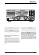
GENERAL The Vertex Standard VX-1700 is a low-cost, integrated HF communications transceiver designed for the worldwide Marine, Land Mobile, and Government markets. The Vertex Standard VX-1700 provides continuous receiver coverage from 30 kHz to 29.99999 MHz, and transmitter coverage as appropriate for the user’s application.
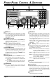
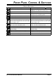
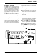
FRONT PANEL CONTROL & SWITCHES MIC Jack SQL Knob This modular jack accepts microphone voice input, as well as scanning and PTT (Push To Talk) control from the microphone. Specified microphone impedance is 500 - 600 Ohms. This control may be used silence the receiver when no signals are being received.
FRONT PANEL CONTROL & SWITCHES KEYPAD FUNCTIONS Key Secondary Function (Press Primary Function (Press Key) +) Selects the Operating Mode. Toggles the IF Bandpass Filter between “WIDE” and “NARROW” in the J2B and A1A modes (only). Toggles the Noise Blanker “on” and “off.” Toggles the Noise Blanker “on” and “off.” Activates the Antenna Tuning Process. Activates the Antenna Tuning Process to the all Memory Channels in the current Memory Bank. Changes the synthesizer step in the VFO mode.
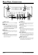
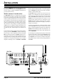
REAR PANEL CONNECTIONS INPUT (13.8 V) TUNER Jack This is the main DC power input jack for the VX-1700. This 8-pin mini-DIN jack is for interconnection to the optional FC-30 or FC-40 External Antenna Tuner. ANT Jack This PL-259 (“M” Type) connector is used for connection of the coaxial feedline from the antenna.
INSTALLATION Safety Precautions Antenna Precautions Before proceeding with installation of the VX-1700 transceiver, please read and observe all safety and operating instructions. Consult with qualified installation or service personnel should any questions arise regarding these important safety tips. Always locate antennas such that they can never come in contact with outdoor power lines in the event of a catastrophic antenna support or power line support structure failure.
INSTALLATION Electromagnetic Compatibility and RF Exposure If this transceiver is used with or in the vicinity of a computer or computer-driven accessories, you may need to experiment with grounding and/or radio frequency interference (RFI) suppression devices (such as ferrite cores) to minimize interference to your communications caused by energy leakage from the computer.
INSTALLATION POWER REQUIREMENTS AND BASIC INSTALLATION DC Power Connections The VX-1700 transceiver is designed for operation from 13.8 Volts DC, negative ground, with the DC source being capable of providing 20 Amperes of continuous current. For mobile applications, the fused (25-A) DC cable supplied with this transceiver may be used for making the power connections.
INSTALLATION MOBILE MOUNTING The optional MMB-89 Mobile Mounting Bracket allows quick insertion and removal of the VX-1700 transceiver from the vehicle. Complete installation instructions are provided with the bracket. provide memory of antenna matching settings sufficient for all channels on Memory Bank 1. In marine applications, the FC-40 is also ideal for the use with a “backstay” antenna or marine mobile whip.
INSTALLATION MOBILE MOUNTING Mobile Station Grounding Although satisfactory grounding in most installations will be achieved via the DC cable’s negative lead and the antenna system’s coaxial cable shield, it may be necessary, in some installations, to provide a direct ground connection at the mounting location of the transceiver. Due to unexpected resonances which may naturally occur in any location, improper communication system performance may result from insufficient grounding.
INSTALLATION BASE STATION INSTALLATION DC Power Connections For base station installations, Yaesu recommends the use of the Model FP-1030A AC Power Supply. The FP1030A provides a regulated 13.8 V DC supply at up to 25-Ampere. Other models of DC power supplies may be used with the VX-1700, but the 13.8 V DC input voltage, 20-Ampere current capability, and DC cable polarity guidelines described previously must be strictly followed.
INSTALLATION BASE STATION INSTALLATION Base Station Antenna Considerations As with mobile or maritime installations, antenna performance is critical to base station communications system effectiveness. Every effort must be made to ensure that the impedance of the antenna system utilized with the VX-1700 is as close as practicable to the specified 50-Ohm impedance value, and that mechanical and electrical component integrity are maintained at all times.
INSTALLATION BASE STATION INSTALLATION Excellent reference texts and computer software are available for the design and optimization of HF antennas. Your dealer or installer should be able to assist you with all aspects of your antenna installation. Use high-quality coaxial cable for the lead-in to your VX1700 transceiver. All efforts at providing an efficient antenna system will be wasted if poor quality, lossy coaxial cable is used.
INSTALLATION NOTE VX-1700 OPERATING MANUAL Page 13
OPERATION STARTUP PROCEDURES RECEPTION Be certain that all power supply, antenna, ground, microphone, and other accessory connections have been properly accomplished. Rotate the VOL and SQL knobs fully counter-clockwise. Turn on the transceiver by press and holding in the POWER Switch. The LCD display will become illuminated. Rotate the VOL knob for a comfortable listening level on the incoming signals or noise present on the speaker.
OPERATION FREQUENCY AND CHANNEL SELECTION The VX-1700 includes the following frequency selection capabilities: A VFO (Variable Frequency Oscillator) System ITU Marine Channel Memory Channel A one-touch (2.182 MHz) Emergency Channel Memory, which places the transceiver on 2.182 MHz (in transceivers configured for Marine use). In the VFO mode, the frequency is displayed on the right side, with the operating mode icon being displayed at the left edge of the display.
OPERATION FREQUENCY AND CHANNEL SELECTION Memory Channel Mode 2.182 MHz Emergency Channel Mode Rotate the CH Selector knob to select the desired Memory Channel within the selected Memory Bank. Remember that there are a total of five Memory Banks, so if you do not find a particular channel, it may have been stored in a different Memory Bank. A special Emergency Channel feature of the VX-1700 provides several important operational benefits for the owner.
OPERATION TRANSMISSION For Voice transmission, close the PTT (Push To Talk) switch on the microphone; the transmitter will now be activated (note that the “ ” icon will be illuminated on the LCD display). Hold the microphone about 1 inch (25 mm) from your mouth, and speak into the front of the microphone in a normal voice level. Release the PTT switch to return to the receive mode (the “ ” icon will be again illuminated, and the “ ” icon will go out).
OPERATION DUAL WATCH The Dual Watch feature allows the user or dispatcher to operate on one channel while periodically making a brief check of Memory Channel “1-001” (Memory Bank #1, Channel #1). The Dual Watch feature can be engaged so long as there is frequency and mode data written into memory channel “1-001.” Every four seconds, the transceiver will automatically switch over to memory channel “1-001.
OPERATION ENCRYPTED TRANSMISSION/RECEPTION (REQUIRES AFTER-MARKETING ENCRYPTION MODULE) If the transceivers you (and others in your communication group) are using are equipped with the aftermarket Encryption Module, the Encryption mode may be activated by pressing the [ ENCR ] key. The “ ” icon will become illuminated. To de-activate encryption, press the [ENCR] key again.
SELCALL/TELCALL OPERATION SELCALL The VX-1700’s Selcall feature provides six calling modes: Selcall The Selcall mode allows you to make an individual/ group call using the individual ID (Identification) number assigned for each transceiver. Message Call The Message Call mode allows you to send a text message (up to 64 characters of text) to another station. Position Request Call The Position Request Call mode allows you to request the position information of another station.
SELCALL/TELCALL OPERATION MESSAGE CALL The Message Call mode allows you to send a text message (up to 64 characters of text) to a specific station. Preparation Rotate the CH Selector knob to select the channel to be used for Message Call. Disable the VOX and Clarifire features, if necessary. Press the [SELCALL] key momentarily to activate the Selcall system. The “ ” icon will be illuminated on the LCD display.
SELCALL/TELCALL OPERATION POSITION REQUEST CALL POSITION SEND CALL The Position Request Call mode allows you to request position information from a specific station. The Position Send Call mode allows you to send your own position information to the intended ID station. Preparation Note: A suitable GPS receiver capable of supplying NMEA-0183 data must be connected to the rear panel’s GPS jack in order to transmit your current position.
SELCALL/TELCALL OPERATION BEACON REQUEST CALL TELCALL The Beacon Request Call mode allows you to inquire as to the signal quality between your transceiver and another specific transceiver (before placing an individual/group call). The Telcall mode allows you to make a telephone call through a telephone interconnect service provider. Preparation Rotate the CH Selector knob to select the channel to be used for the Beacon Request Call. Disable the VOX and Clarifire features, if necessary.
ALE OPERATION (REQUIRES OPTIONAL ALE-1 UNIT) The VX-1700’s ALE (Automatic Link Establishment) feature allows you to select the channel with the best LQA (Link Quality Analysis) score from the programmed channels automatically. Sending an ALE Call Press the [7(V/M)] key, as needed, to select the Memory Channel mode. Press the [AEL] key momentarily to activate the ALE feature. The VX-1700 will display the last-activated network.
MEMORY CHANNEL STORAGE Press the [7(V/M)] key, as needed, to select the Memory Channel mode. Press the [9(M/W)] key; on the LCD, you will see a blinking memory channel number. Rotate the CH Selector knob to select the Memory channel onto which you wish to store new frequency information. If you select a channel on which data is already stored, entering new data will cause you to overwrite the data previously stored.
PROGRAMMABLE FUNCTION (PF) KEYS The VX-1700 includes four Programmable Function (P1 ~ P4) Keys. The Programmable Function button functions can be customized, via programming by your VERTEX STANDARD dealer, to meet your communications/network requirements. Some features may require the purchase and installation of optional internal accessories. The possible Programmable Function button programming features are illustrated below, and these functions are explained follow.
PROGRAMMABLE FUNCTION (PF) KEYS VOX Press the assigned programmable key to toggle the VOX feature “on” and “off.” The “ ” icon will appear on the display when the VOX feature is activated. ALE Press the assigned programmable key to toggle the ALE (Automatic Link Establishment) feature “on” and “off.” CALL Press the assigned programmable key to transmit a Selcall (or ALE) while operating in the Selcall (or ALE) mode.
NOTE Page 28 VX-1700 OPERATING MANUAL
Copyright 2012 Vertex Standard LMR, Inc. All rights reserved No portion of this manual may be reproduced without the permission of Vertex Standard LMR, Inc. Printed in Japan.