VERTEX STANDARD CO., LTD. 4-8-8 Nakameguro, Meguro-Ku, Tokyo 153-8644, Japan VERTEX STANDARD VX-1700 Series US Headquarters 10900 Walker Street, Cypress, CA 90630, U.S.A. YAESU UK LTD. HF Multi Mode Mobile Radio Service Manual For USA Version ©2011 VERTEX STANDARD CO., LTD. Unit 12, Sun Valley Business Park, Winnall Close Winchester, Hampshire, SO23 0LB, U.K. VERTEX STANDARD HK LTD. Unit 1306-1308, 13F.
Specifications General Receiver Frequency Range: Transmitter Frequency: Emission Modes: Frequency Synthesizer Step: Frequency Stability: Operating Temperature Range: Antenna Impedance: Supply Voltage: Power Consumption: Dimensions (WxHxD): Weight (approx.): 30 kHz ~ 30.0000 MHz 1.600 ~ 30.0000 MHz A1A (CW), J3E (LSB/USB), A3E (AM), J2B (USB/LSB) 10 Hz, 100 Hz, 1 kHz ±1 ppm (Typical) 14° F ~ 131° F (–10° ~ +55° C) @Duty Cycle TX:RX = 1 min.: 4 min. 50 Ohms 13.
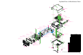
Exploded View & Miscellaneous Parts 14 14 14 14 14 RA0695200 COVER (TOP) 14 14 13 RA0809600 SPONGE RUBBER 14 1 13 2 RA0809600 SPONGE RUBBER 13 13 P1091335 CONNECTOR (FM-MDR-MI) 6 PA UNIT RA0809600 SPONGE RUBBER 6 6 13 RA0809600 SPONGE RUBBER 6 3 15 5 RA0635400 CHASSIS RA0695600 HOLDER PLATE (CW) 5 T9207202A WIRE ASSY PANEL UNIT RA0695700 HOLDER PLATE (D-SUB) 12 RA069610A REFLECTOR SHEET RA0727200 DIFFUSER SHEET (BLIND) (2pcs) 9 4 RA0695800 INTER CONNECTOR (2pcs) 9 G6090162 LCD
Exploded View & Miscellaneous Parts Note 4
Block Diagram 5
Connection Diagram 6
Circuit Description Receive Signal Path Incoming RF signal from the ANT jack is delivered to the PA Unit, and passes through the TX/RX relay RL2009 to J2006.
Circuit Description On the PA Unit, the low-level RF signal from the MAIN Unit is amplified by pre-driver Q2001 (RD06HHF1), push-pull driver Q2008/Q2009 (both RD16HHF1), and push-pull final amplifier Q2012/ Q2013 (both SD1405), which provides up to 120 watts of RF output power. The RF output from the final amplifier is fed through the one of seven low-pass filters, sampling directional coupler T2005, and TX/RX relay RL2009 before delivery to the antenna jack.
Circuit Description Control Circuit TX/RX Control Major frequency control functions such as channel selection, display, and PLL divider control are performed by main CPU Q1018 (HD64F2134) on the MAIN Unit, at the command of the user via the tuning knob and function switches on the front panel. When the PTT switch is pressed, pin 21 of the main CPU Q1018 (HD64F2134) goes low, which causes pin 60 of the main CPU Q1018 (HD64F2134) to go low. This signal disables the receiver 12 V bus at Q1046 (2SA1602A).
Connector Pinout Diagrams MIC Jack GPS Jack (As Viewed From Front Panel) (As Viewed From Rear Panel) Connected with , , , and . GPS Data Input. N/C (Lot. 1~25) GPS Data Output (Lot. 26 & 27 : When the firmware is updated. GPS Data Output (Lot. 28~) Connected with , , , and . GPS Data. Connected with , , , and . Connected with , , , and . Connected with , , , and . N/C (Lot. 1~25) GND (Lot.
Alignment The VX-1700 is carefully aligned at the factory for the specified performance across the entire operating frequency range. Realignment should therefore not be necessary except in the event of a component failure. All component replacement and service should be performed only by an authorized Vertex Standard representative, or the warranty policy may be void. ed, the interactions of some adjustments may require that more complex adjustments be performed afterwards.
Alignment Whenever possible, alignments should be made with oscillator shields and circuit boards firmly affixed in place. Also, the test equipment must be thoroughly warmed up before beginning. Note: Signal levels in dB referred to in the alignment procedure are based on 0dBµ = 0.5µV. Set up the test equipment as shown below, and apply 13.8V DC power to the transceiver. The VX-1700 must be programmed for use in the intended system before alignment is attempted.
Alignment Transmitter Alignment Receiver Alignment TX IF COILS ALIGNMENT RX IF COILS ALIGNMENT Connect the 50 Ohm Dummy Load to the ANT jack. Remove the coaxial plug from J1002 on the MAIN Unit, then connect the RF millivoltmeter and 50 Ohm resistor to J1002. Connect the AF Generator to pin 4 of the MIC jack. Tune the radio to 7.500 MHz, USB mode. Inject a 0.5 mVrms @1 kHz audio signal from the AF Generator.
Alignment DRIVER SECTION IDLING CURRENT ALIGNMENT PA Unit Alignment PRE-DRIVER SECTION IDLING CURRENT ALIGNMENT Connect the 50 Ohm Dummy Load to the ANT jack. Remove the shorting-plug from J2003 on the PA Unit, then connect the DC Ammeter to J2003 (pin 1: “–” lead, pin 2: “+” lead). Set VR2001 on the PA Unit fully counter-clockwise. Tune the radio to 7.500 MHz, USB mode.
Alignment FINAL SECTION IDLING CURRENT ALIGNMENT CM COUPLER BALANCE Connect the 50 Ohm Dummy Load to the ANT jack. Remove the solder jumper which is connected between TP2020 and TP2021 on the PA Unit, then connect the “+” lead of the DC Ammeter to TP2020 and the “–” lead to TP2021. Set VR2003 on the PA Unit fully counter-clockwise. Tune the radio to 7.500 MHz, USB mode.
Alignment Software Menu Alignment The ANT jack should be connected to a Dummy Load (in the case of transmission) or RF Signal Generator (in the case of reception). General alignment conditions are as follows, unless otherwise noted. VOL Knob: Center (12 o’clock position). SQL Knob: Fully counter-clockwise. TX Output Power: HIGH VOX:Off The channel data in the radio is preset per the chart below. Connect the 50 Ohm Dummy Load and Inline Wattmeter to the ANT jack.
Alignment TX GAIN ALIGNMENT REV ALC ALIGNMENT Connect the 50 Ohm Dummy Load and Inline Wattmeter to the ANT jack. Connect the AF Generator to pin 4 of the MIC jack, and adjust the AF Generator output level to 0.5 mV @1 kHz. Referring to the Table below, press the [T]/[S] key to recall each parameter listed, then key the transmitter (connect pin 3 of the MIC jack to GND) and rotate the CH knob for the required output.
Alignment Note 18
ALE-1 Automatic Link Establishment Unit Installation Installation Make sure that the transceiver off. Remove the DC Power Cable, Microphone, and Antenna from the transceiver. Referring to Figure 1, remove the four screws from the side of the transceiver (two screws for each side), along with four screws affixing the bottom case; remove the bottom case.
ALE-1 Automatic Link Establishment Unit Installation Note 20
CE77 PC Programming Software The CE77 PC Programming Software is used to program the VX-1700 HF Communications Transceiver. With the CE77 PC Programming Software, you can quickly and easily program the Vertex Standard VX-1700 operating channels and configuration from your personal computer. In the event of an accidental memory failure, channel memory and configuration data may be re-loaded in a matter of minutes.
CE77 PC Programming Software MODE This column selects the Operating Mode. To select the Operating Mode, double click the left mouse button on this column to invoke a pop-up window, select the desired Operating Mode, then click the [OK] button to accept the new Operating Mode. The available selections are “J3E (USB),” “J3E (LSB),” “J2B,” “A1A,” and “A3E.” FILTER This column selects the bandwidth of the IF filter.
CE77 PC Programming Software Main Programming Screen (Memory Screen) CHN (CHANNEL) This number is used to identify the memory channel. They do not have to occur in order, and you can duplicate numbers from other groups (do not duplicate within a group). For example, each group may have a channel 1, but a particular group may not have two channel 4s. Double click the left mouse button to toggle lock the channel lock between “Enable” and “Disable.
CE77 PC Programming Software RECEIVE FREQUENCY This column is used for entry of the Receive Frequency. To enter the Receive Frequency, double click the left mouse button on this column, enter the desired Receive Frequency from the keyboard, then press the [ENTER] key to lock in the new frequency. The available values are “0.0300 (MHz)” to “30.0000 (MHz).” TRANSMIT FREQUENCY This column is used for entry of the Transmit frequency.
CE77 PC Programming Software File Menu NEW Opens a new file. Click the left mouse button on the “New” parameter in the File menu; this will open the default configuration of the CE77 software. Shortcuts Toolbar: Keys: CTRL+N OPEN Opens a previously-saved configuration from the disk. Click the left mouse button on the “Open” parameter in the File menu; a pop-up window will appear which shows you all the current files saved in the specified path.
CE77 PC Programming Software Edit Menu View Menu COPY Use this command to copy selected data onto the clipboard. This command is unavailable if there is no data currently selected. Copying data to the clipboard replaces the contents previously stored there. Shortcuts Toolbar: Keys: CTRL+C TOOL BAR The toolbar is displayed across the top of the application window, below the menu bar. The toolbar provides quick mouse access to many tools used in CE77.
CE77 PC Programming Software Common Menu A1A (CW) FUNCTION PARAMETERS This parameter programs the various configuration items of the A1A (CW) mode. Put a check mark into the check box to enable adjustment of its parameter from the transceiver’s set (“menu”) mode. The available parameters are: CW Delay, CW QSK, Side Tone SET, and Side Tone Level. CW DELAY This parameter sets the CW delay time.
CE77 PC Programming Software HARDWARE PARAMETERS Put a check mark into the check box to enable adjustment of its parameter from the transceiver’s set (“menu”) mode. The available parameters are: 1.6 - 4 MHz RF Power, 4 - 30 MHz RF Power, Dimmer Level-1, and Dimmer Level-2. 1.6 - 4 MHz RF POWER This parameter programs the TX output power on the 1.6 - 4 MHz band for each power setting level.
CE77 PC Programming Software KEY FUNCTION PARAMETERS This parameter sets the configurations for the keypad and button functions of the radio. Put a check mark into the check box to enable adjustment of its parameter from the transceiver’s set (“menu”) mode. The available parameters are: P1 SET, P2 SET, P3 SET, P4 SET, and PU/D SET. P1 SET - P4 SET This parameter programs the Programmable Function Button feature.
CE77 PC Programming Software MARKETING PARAMETERS This parameter indicates the Market Application Number and Serial Number of the radio. The available parameters are Market Applications and Serial Number. MARKET APPLICATIONS This parameter indicates the Alpha/numeric “Tag” (up to 16 digits) used for identifying the owner or application of the radio. SERIAL NUMBER This parameter presently is not supported. It will be used in the future.
CE77 PC Programming Software BEEP TONE This parameter sets the Beep Tone (frequency). The available selections are “LOW,” “NORMAL,” and “HIGH.” SCAN RESUME This parameter selects the Scan Resume Mode. The available selections are “Carrier” and “Timer.” BEEP AF SET This parameter defines whether the Beep volume is linked to the front panel’s VOL knob (“LINK”) or not linked (“FIX”). STANDBY BEEP This parameter toggles the Standby Beep feature “ON” or “OFF.
CE77 PC Programming Software SYSTEM PARAMETERS This parameter programs the various system configurations of the radio. Put a check mark into the check box to enable adjustment of its parameter from the transceiver’s set (“menu”) mode. The available parameters are: APO, Clarifier Backup Type, Carrier Offset, Display Offset, J2B MODE, MIC Gain, Password Set, SP Mute Act, SP Mute Level, TOT, Tuning, VFO, VOL Limit, DEALER MODE, RETURN, CLOCK SHIFT, DW CH SEL, ENCRPT CODE, and MEMORY WRITE.
CE77 PC Programming Software MIC GAIN This parameter programs the Microphone Input Sensitivity. The available values for the Microphone Gain are “LOW,” “NORMAL,” or “HIGH.” PASSWORD SET This parameter programs the password for the entering to the Dealer mode of the transceiver. To enter the password, double click the left mouse button on this column, enter the desired password (four digits; numeric only) from the keyboard, then press the [ENTER] key to accept the new password.
CE77 PC Programming Software DW CH SEL This parameter defines whether the “DW CH SEL” selection shall be “Enabled” or “Disabled” from the transceiver’s set (“menu”) mode. ENCRPT CODE This parameter defines whether the “ENCRPT CODE” selection shall be “Enabled” or “Disabled” from the User Set Mode. MEMORY WRITE This parameter defines whether the “MEMORY WRITE” selection shall be “Enabled” or “Disabled” from the User Set Mode.
CE77 PC Programming Software Selcall Menu SELCALL PARAMETERS This parameter programs the various Selcall configurations of the radio. Put a check mark into the check box to enable adjustment of its parameter from the transceiver’s set (“menu”) mode. Note: The Selcall is only activated on the J3E mode. The available parameters are Selcall, Kill System, Stun System, Beacon Request, GPS Position Request.
CE77 PC Programming Software GPS POSITION REQUEST This parameter determines whether the radio is able to receive or transmit a GPS position request. The available selections are “RX,” “TX,” “TX+RX,” and “OFF.” RX: Enables the receiving of a GPS position request and disable the sending of a GPS position request. TX: Enables the sending of a GPS position request and disables the receiving of a GPS position request. TX+RX: Enables both the receiving and sending of a GPS position request.
CE77 PC Programming Software ALL CALL This parameter determines whether the “All Call” function of the Selcall feature shall be “Enabled” or “Disabled”. ANSWER BACK This parameter determines whether the “Answer Back” function shall be “Enabled” or “Disabled” when receiving a Selcall. GROUP CALL This parameter determines whether the “Group Call” function of the Selcall feature shall be “Enabled” or “Disabled.
CE77 PC Programming Software TX ID PARAMETER This parameter programs the Selcall TX ID to be called. To program this parameter, enter the TX ID (4 digits) into the “TX ID” column, then set the desired effective channel range (i.e. 1-001, 1-050, 2-051, etc.) for the TX ID into the “FROM” and “TO” columns. Enter the Alpha/Numeric Tag (8 digits) of the TX ID into the “TAG” column, if desired. "TX ID" PARAMETERS TELEPHONE NUMBER PARAMETERS This parameter programs the telephone number for the Telcall feature.
CE77 PC Programming Software ALE Menu ALE COMMON PARAMETERS This parameter programs the various configurations for the ALE (Automatic Link Establishment) system of the radio. The ALE system allows the radio to select the channel with the best LQA (Link Quality Analysis) score from the programmed channels. Put a check mark into the check box to enable adjustment of its parameters from the transceiver’s set (“menu”) mode.
CE77 PC Programming Software NET NUMBER Put a check mark into the check box to enable adjustment of its parameter from the transceiver’s set (“menu”) mode. AMD MESSAGE PARAMETERS This parameter programs the Alpha/Numeric messages in accordance with the AMD definition. To enter the Alpha/Numeric message, double click the left mouse button on the desired column, type the characters of the desired Alpha/Numeric message (up to 90 characters), then press the [ENTER] key to save the programmed “message.
CE77 PC Programming Software ALE MISCELLANEOUS PARAMETERS This parameter programs the various configurations for the ALE (Automatic Link Establishment) system of the radio. Put a check mark into the check box to enable adjustment of these parameters from the transceiver’s set (“menu”) mode. The available parameters are Net Number, Sounding, All Call Set, LQA Request, Master/Slave, Net Name, Occupancy Detection, Self Address, Silent Mode, Scan Rate, and Tune Time.
CE77 PC Programming Software SILENT MODE This parameter defines whether the Silent mode shall be “Enabled (SILENT)” or “Disabled (NORMAL).” When this parameter is set to “Enabled (SILENT),” the network can initiate calls but the network is not allowed to respond to an ALE transmission. SCAN RATE This parameter toggles the scan speed between the “2 sec/ch” (2 seconds per channel) and “5 sec/ ch” (5 seconds per channel) when the radio is in the ALE mode.
CE77 PC Programming Software NET MEMBER ADDRESS PARAMETER This parameter defines the network member address to be called. To enter the network nember address, select the network from the pull-down list, then double click the left mouse button on the desired bank to invoke a pop-up window, select the desired address, then click the [OK] button to accept the address.
CE77 PC Programming Software Channel Menu Radio Menu CHANNEL ALLOCATION PARAMETER The VX-1700 is capable of allocating up to 200 channels into 5 banks. By default, Bank-1 is filled with all memories (200 channels); Bank-2 through Bank-5 are disabled (empty). Bank-2 will be enabled once Bank-1 is filled to capacity, and will start being filled by the extra memories carried over. UPLOAD PARAMETER Reads the configuration data from the radio to the computer.
CE77 PC Programming Software DOWNLOAD PARAMETER Writes the configuration data from the computer to the radio. Data will be verified for integrity by the program before downloading is initiated. NOTE: Make sure to select the correct communications port to ensure proper operation. The program will lock-up if there is a conflict between the mouse port and PC Programming Cable Port. Shortcuts Toolbar: REVIVE PARAMETER This parameter returns the radio to the normal mode from the STUN mode.
CE77 PC Programming Software Programming Example 1 Selcall Feature Basic Setup 1. Assign the “SELCALL” function into the “Programmable Function key 1 (P1 SET)” and the “CALL” function to the “Programmable Function key 2 (P2 SET)” from the “KEY FUNCTION” parameter in the “Common” menu. 2. Set the “SELCALL” parameter in the “Selcall” menu to the “TX+RX” option, to enable the receiving and sending of a Selcall. 3.
CE77 PC Programming Software Programming Example 2 ALE Feature Basic Setup 1. Set the “Optional Board” parameter which is located in the “Option” folder in the “Common” menu to the “ALE Unit” to activate the optional ALE-1 Unit. 2. Set the “ALE” parameter in the “ALE Common” folder in the “ALE” menu to “ON” to enable the ALE feature. 3. Enter the Network Address to be used into the “Net Name” parameter in the “ALE Miscellaneous” folder in the “ALE” menu. 4.
CE77 PC Programming Software Programming Example 3 Programming Example 5 Kill Command Setup Enter the Kill Command (CILLIK) and Radio ID (ex. TEST6111) into the “Message” parameter on the “Selcall” folder in the “Selcall” menu. Revive Command Setup Enter the Revive Command (SVIVER) and Radio ID (ex. TEST6111) into the “Message” parameter on the “Selcall” folder in the “Selcall” menu. Programming Example 4 Stun Command Setup Enter the Stun Command (ECNUTS) and Radio ID (ex.
MAIN Unit (Lot.
MAIN Unit (Lot.
MAIN Unit (Lot.
MAIN Unit (Lot.
MAIN Unit (Lot.
MAIN Unit (Lot.
MAIN Unit (Lot. 19~) Parts Layout (Side A) A AK4528VF (Q1071) HD64F2134 (Q1018) UPD77115GK (Q1035) L78M05T (Q1008) UPC2926T (Q1006) 2SC2714 (QY) 2SC2954(QK)(Lot.1-18) (Q1016, 1021, 1023, 2SC5415E (EA) (Lot. 1026, 1027, 1063, 19-) 1064, 1070, 1074, (Q1001, 1029) 1075) 2SC3357 (RK) 2SC2812 (LG) (Q1025) (Q1002, 1044) 2SD2211 (DQR) 2SC3356 (R24) (Q1076) (Q1028) TDA2003H (Q1055) C BA05FP (Q1012) D E TC7S04FU (E5) (Q1059, 1062) F G H I J K TC7ST08FU (Q1080) (Q1031:Lot.
MAIN Unit (Lot.
MAIN Unit Parts List REF. DESCRIPTION VALUE V/W TOL.
MAIN Unit Parts List REF.
MAIN Unit Parts List REF.
MAIN Unit Parts List REF.
MAIN Unit Parts List REF.
MAIN Unit Parts List REF.
MAIN Unit Parts List REF.
MAIN Unit Parts List REF.
MAIN Unit Parts List REF.
MAIN Unit Parts List REF.
MAIN Unit Parts List REF.
MAIN Unit Parts List REF.
MAIN Unit Parts List REF.
MAIN Unit Parts List REF.
MAIN Unit Parts List REF.
MAIN Unit Parts List REF.
MAIN Unit Parts List REF.
MAIN Unit Parts List REF.
MAIN Unit Parts List REF. DESCRIPTION R 1397 R 1399 R 1998 R 1999 S 1001 T 1001 T 1001 T 1002 T 1002 T 1003 T 1003 T 1004 T 1004 T 1005 T 1006 T 1006 T 1007 T 1007 T 1008 T 1009 T 1010 T 1011 T 1012 T 1013 TH1001 X 1002 X 1003 X 1004 X 1004 XF1001 CARBON FILM RES. CHIP RES. CHIP RES. CHIP RES. DIP SWITCH COIL WIDE-TRANS. COIL WIDE-TRANS. COIL WIDE-TRANS. COIL WIDE-TRANS. COIL WIDE-TRANS. COIL WIDE-TRANS. COIL WIDE-TRANS. COIL WIDE-TRANS. COIL WIDE-TRANS. COIL WIDE-TRANS. COIL WIDE-TRANS. COIL WIDE-TRANS.
MAIN Unit Note 76
PA-2 Unit (Lot.
PA-2 Unit (Lot.
PA-2 Unit (Lot.
PA-2 Unit (Lot.
PA-2 Unit (Lot.
PA-2 Unit (Lot.
PA-2 Unit (Lot.
PA-2 Unit (Lot.
PA-2 Unit Parts List REF. DESCRIPTION VALUE V/W TOL.
PA-2 Unit Parts List REF.
PA-2 Unit Parts List REF.
PA-2 Unit Parts List REF.
PA-2 Unit Parts List REF.
PA-2 Unit Parts List REF. R 7043 R 7044 R 7045 R 7046 R 7047 R 7048 R 7049 R 7050 R 7051 R 7052 R 7053 R 7054 R 7075 R 7077 RL7001 RL7002 RL7003 RL7004 RL7005 RL7006 RL7007 RL7008 RL7009 RL7010 RL7011 RL7012 RL7013 RL7014 RL7015 RL7016 T 7001 T 7002 T 7002 T 7003 T 7004 T 7005 TC7001 TC7001 TH7001 TP7019 TP7020 TP7020 TP7021 VR7001 VR7001 VR7002 VR7003 VR7003 90 DESCRIPTION METAL FILM RES. CHIP RES. CHIP RES. CHIP RES. CHIP RES. CHIP RES. CHIP RES. CHIP RES. CHIP RES. CHIP RES. CHIP RES. CHIP RES.
PANEL Unit Circuit Diagram 91
PANEL Unit Note 92
PANEL Unit Parts Layout (Side A) A B C D E F G H I 1 2 3 4 93
PANEL Unit Parts Layout (Side B) a b c 1 2 3 4 2SC4154 (E) (Q3005) 94 CPH6102 (AB) (Q3005) DTC143ZE (E23) (Q3006) LC75884W (Q3001) d e f g h i
PANEL Unit Parts List REF.
PANEL Unit Parts List REF. S 3009 S 3010 S 3011 S 3012 S 3013 S 3014 S 3015 S 3016 S 3017 S 3018 S 3019 S 3020 S 3021 S 3022 96 DESCRIPTION TACT SWITCH TACT SWITCH TACT SWITCH TACT SWITCH TACT SWITCH TACT SWITCH TACT SWITCH TACT SWITCH TACT SWITCH TACT SWITCH TACT SWITCH TACT SWITCH TACT SWITCH TACT SWITCH DIFFUSER SHEET REFLECTOR SHEET LIGHT GUIDE LCD HOLDER REFLECTOR SHEET REFLECTOR SHEET INTER CONNECTOR SPONGE RUBBER VALUE V/W TOL.
GPS-INTERFACE Unit (Lot.
GPS-INTERFACE Unit (Lot.
GPS-INTERFACE Unit (Lot.
GPS-INTERFACE Unit (Lot.
GPS-INTERFACE Unit (Lot.
GPS-INTERFACE Unit (Lot.
GPS-INTERFACE Unit (Lot.
GPS-INTERFACE Unit (Lot.
GPS-INTERFACE Unit (Lot.
GPS-INTERFACE Unit Parts List REF. DESCRIPTION VALUE V/W TOL.
MIC Unit Circuit Diagram Parts Layout Side A Side B Parts List REF. J 6001 J 6002 DESCRIPTION PCB with Components Printed Circuit Board CONNECTOR CONNECTOR VALUE V/W TOL. MFR’S DESIG AC051H000 R41-2509R B8B-ZR-SM3-TFT VXSTD P/N CB3199001 FR0136100 P1091243 P0091414 VERS. LOT.
ENC Unit Circuit Diagram Parts Layout Side A Side B Parts List REF. C 6101 J 6101 S 6101 VR6101 VR6102 108 DESCRIPTION PCB with Components Printed Circuit Board CHIP CAP. CONNECTOR ROTARY ENCODER POT. POT. VALUE 0.1uF V/W 16V TOL. B MFR’S DESIG VXSTD P/N AC051H000 GRM188B11C104KA01D 52746-0890 EC11B15204AU RH96N74 23F B103 RY-7862 RH96N220 23F B103 RY-7861 CB3200001 FR0136200 K22124805 P1091163 Q9000837 J60800285 J60800284 VERS. LOT.
ALE Unit (Option) Circuit Diagram 109
ALE Unit (Option) Parts Layout Parts Layout (Side B) A B C D E F a 1 1 2 2 3 3 4 4 Side A 110 HD64F2134 (Q4009) ADM202EARU (Q4009) NJM2902V (Q4007) BR24L64F (Q4008) M51945BFP (Q4002) TC7W14FU (Q4019) BA05FP (Q4005) LH52256CT (Q4001) 2SC4047 (ZY) (Q4006) 2SC4154 (E) (Q4003, 4010, 4012, 4021) 2SD2211 (DQR) (Q4004) TC7S04FU (E5) (Q4023) MC2850 (A7) (D4010) b c d e f Side B
ALE Unit (Option) Parts List REF. DESCRIPTION Printed Circuit Board CHIP CAP. CHIP CAP. CHIP CAP. CHIP CAP. CHIP CAP. CHIP CAP. CHIP TA.CAP. AL.ELECTRO.CAP. AL.ELECTRO.CAP. CHIP CAP. CHIP CAP. CHIP CAP. CHIP CAP. CHIP CAP. CHIP CAP. CHIP CAP. AL.ELECTRO.CAP. CHIP CAP. CHIP TA.CAP. AL.ELECTRO.CAP. CHIP CAP. CHIP CAP. CHIP CAP. CHIP CAP. CHIP CAP. CHIP CAP. CHIP CAP. CHIP CAP. CHIP CAP. CHIP CAP. CHIP CAP. CHIP CAP. CHIP CAP. CHIP CAP. CHIP TA.CAP. CHIP TA.CAP. CHIP CAP. AL.ELECTRO.CAP. CHIP CAP. CHIP CAP.
ALE Unit (Option) Parts List REF.
ALE Unit (Option) Parts List REF. R 4075 R 4076 R 4077 R 4078 R 4079 R 4080 R 4081 R 4082 R 4083 R 4084 R 4085 R 4086 R 4087 R 4088 R 4089 R 4090 R 4091 R 4092 R 4093 R 4094 R 4095 R 4096 R 4097 R 4098 R 4099 R 4100 R 4101 R 4102 R 4103 R 4104 R 4105 R 4106 R 4107 R 4108 R 4109 R 4117 R 4122 R 4135 R 4137 R 4139 R 4140 R 4141 R 4142 R 4143 R 4144 R 4145 R 4146 R 4147 R 4148 R 4149 R 4150 R 4152 R 4153 S 4001 S 4002 S 4003 S 4004 X 4001 DESCRIPTION CHIP RES. CHIP RES. CHIP RES. CHIP RES. CHIP RES. CHIP RES.
ALE Unit (Option) Note 114
Copyright 2011 VERTEX STANDARD CO., LTD. All rights reserved No portion of this manual may be reproduced without the permission of VERTEX STANDARD CO., LTD.