VX-2200 SERIES OPERATING MANUAL VERTEX STANDARD CO., LTD. 4-8-8 Nakameguro, Meguro-Ku, Tokyo 153-8644, Japan VERTEX STANDARD US Headquarters 10900 Walker Street, Cypress, CA 90630, U.S.A. YAESU EUROPE B.V. P.O. Box 75525, 1118 ZN Schiphol, The Netherlands YAESU UK LTD. Unit 12, Sun Valley Business Park, Winnall Close Winchester, Hampshire, SO23 0LB, U.K. VERTEX STANDARD HK LTD. Unit 5, 20/F.
Congratulations! You now have at your fingertips a valuable communications tool: a VERTEX STANDARD two-way radio! Rugged, reliable and easy to use, your VERTEX STANDARD radio will keep you in constant touch with your colleagues for years to come, with negligible maintenance downtime. Please take a few minutes to read this manual carefully. The information presented here will allow you to derive maximum performance from your radio, in case questions arise later on.
INTRODUCTION The VX-2200 Series are full-featured FM transceivers designed for flexible mobile and base station business communications in the VHF or UHF Land Mobile bands. These transceiver are designed for reliable business communications in a wide variety of applications with a wide range of operating capability provided by their leading-edge design. The 128-channel memories can each be programmed with a 8-character channel name.
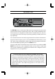
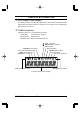
CONTROLS & CONNECTORS Front Panel Important! - All buttons located on the Front Panel are Programmable Function (PF) Buttons, configured according to your network requirements and programmed by your VERTEX STANDARD dealer. The instructions below describe a typicallyconfigured radio. VOL/PWR Knob Turn this control clockwise to turn the radio on and to increase the volume. Turn it counterclockwise into the click-stop to turn the radio off.
CONTROLS & CONNECTORS LCD (Liquid Crystal Display) The display includes a 8-character alpha-numeric section showing Channel name tags/identity information and error messages, and an upper icon row displaying feature status (see below).
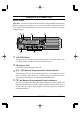
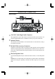
CONTROLS & CONNECTORS Rear Panel 13.6V DC Cable Pigtail with Connector The supplied DC power cable must be connected to this 2-pin connector. Use only the supplied fused cable, extended if necessary, for power connection. Antenna Socket The 50-Ohm coaxial feedline to the antenna must be connected here, using a type-M (PL-259) plug.
BASIC OPERATION OF THE TRANSCEIVER Important! - Before turning on the radio the first time, confirm that the power connections have been made correctly and that a proper antenna is connected to the antenna jack. Switching Power ON/OFF Turn the VOL/PWR knob turn on the radio. The display will become illuminated. Press the [ ]/[ ] button to choose the desired operating channel. A channel name will appear on the display.
BASIC OPERATION OF THE TRANSCEIVER Automatic Time-Out Timer If the selected channel has been programmed for automatic time-out, you must limit the length of each transmission. While transmitting, a beep will sound 10 seconds before time-out. Another beep will sound just before the deadline; the red “TX” indicator will disappear and transmission will cease soon thereafter.
ADVANCED OPERATION Function MONI SQL OFF SQL SET DIMMER Channel Up Channel Down Continuous Ch Up Continuous Ch Down Group Up Group Down SCAN SCAN SET Group SCAN Group SCAN SET DW (Dual Watch) Follow-Me SCAN Follow-Me DW LOW TA (Talk Around) TA SCAN Encryption Emergency RESET CALL 1 CALL 2 CALL 3 DTMF CODE SET Code Up Code Down Code SET Speed Dial Public Address EXT. ACC1 EXT.
ADVANCED OPERATION Description of Operating Functions MONITOR (MONI) Press (or press and hold) the assigned programmable key to cancel CTCSS- and DCS-controlled squelch; the TX/BUSY indicator will glow green SQUELCH (SQL) OFF Press (or press and hold) the assigned programmable key to open the SQL to hear background noise (unmute the audio); the TX/BUSY indicator will blink green.
ADVANCED OPERATION CHANNEL SCAN (SCAN) The Scanning feature is used to monitor multiple channels programmed into the transceiver. While scanning, the transceiver will check each channel for the presence of a signal, and will stop on a channel if a signal is present. To activate scanning: Press (or press and hold) the assigned programmable key to activate scanning on the current group.
ADVANCED OPERATION GROUP SCAN SET You may wish to have the Scanner pass through more than one Group during the scanning process (normally, scanning is performed within the current group only). To include the current Group in the scanning loop, press (or press and hold) the assigned programmable key. To remove a Group from Group Scan, press (or press and hold) the assigned programmable key again.
ADVANCED OPERATION FOLLOW-ME DUAL WATCH (DW) To set up a “Dual Watch” frequency pair using the “Follow-Me” feature, select a channel using the Channel Up/Down key (generally the [ ]/[ ] button). Now press (or press and hold) the assigned programmable key; pressing the assigned programmable key locks the current channel as the User-assigned Priority Channel. Now press (or press and hold) the Channel Up/Down key to select another channel (not the “Scanning Start” channel).
ADVANCED OPERATION TA SCAN The “TA SCAN” is one of “DW Scan” between Rx and Tx frequency. It works the Rx channel as priority channel and the radio will always transmit on the Tx Channel if the PTT is pressed in the TA SCAN mode. Press (or press and hold) the assigned programmable key to activate/deactivate the TA SCAN feature. ENCRYPTION (OPTION) When the Voice Scrambler feature is enabled, press (or press and hold) the assigned programmable key to toggle the voice encryption on and off.
ADVANCED OPERATION CODE SET Press (or press and hold) the assigned programmable key to change the 5-Tone encodeing digit. To change the tones, select the desired digit using the [P1]/[P2] keys, then change the number using the [ ]/[ ] keys. SPEED DIAL Your Dealer may have pre-programmed Auto-Dial telephone number memories into your radio.
ADVANCED OPERATION AF MIN VR Press (or press and hold) the assigned programmable key to reduce the audio output to the (lower) level programmed by your Dealer. LONE WORKER Press (or press and hold) the assigned programmable key to toggle the Lone Worker feature “On” and “Off.” The Lone Worker feature is designed to emit an alarm for 30 seconds when the Lone Worker Timer (programmed by your Dealer) has expired.
ADVANCED OPERATION ARTS (Auto Range Transpond System) This system is designed to inform you when you and another ARTS-equipped station are within communication range. During ARTS operation, when the radio receives an incoming ARTS signal, a short beep will sound, and “IN SVC” (“In Service”) will be displayed on the LCD for 2 seconds.
USER SET MODE The VX-2200 Series includes a “User Set” (Menu) Mode which allows the user to define or configure various settings, such as Squelch, Display contrast, etc. To activate the “User Set” (Menu) Mode: Press the programmable key assigned to the “SET” function. Select the User Set Mode item you wish to change using the [P1]/[P2] keys, then use the [ ]/[ ] keys to adjust the setting of the selected item. Press the [P1] or [P2] key to store the new configuration.
OPTIONAL ACCESSORIES MH-67A8J MH-25A8J MH-64A8J MD-11A8J MLS-100 MLS-200 FP-1023A FVP-25 FVP-36 FVP-35 VME-100 VT60FS VT60F LF-1 VPL-1 CE82 FIF-10A CT-104A Standard Microphone Standard Microphone 16 Keypad Microphone Desktop Microphone External Speaker (12 W Peak Power) External Speaker (15 W Peak Power) External Power Supply (13.
Copyright 2006 VERTEX STANDARD CO., LTD. All rights reserved. No portion of this manual may be reproduced without the permission of VERTEX STANDARD CO., LTD.