
Service manual


7
Operating Manual Reprint
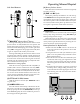
INSTALLING CHANNEL-STOPS
To simplify operation and prevent selection of unpro-
grammed/unused channels or channel groups, tiny met-
al inserts or “stops” can be inserted into the top panel
beneath the CH selector knob. A tiny tab protruding from
beneath the skirt of the CH knob engages the stop(s) as it
is turned, preventing further rotation.
To insert a stop, rotate the CH knob to the channel “1”
position and use the Allen wrench to loosen the setscrew
locate the CH knob, then pull off the CH knob. Insert the
stops firmly into the appropriate slot(s) for the desired
channels, using a pair of tweezers or fine needle-nose pli-
ers, according to the drawing below. For example, to lim-
it CH selection to channels 1 - 4, insert one metal stop at
the slot 16 (channel 1 minus “one position”), and the other
at the slot 3 (channel 4 minus “one position”). When done,
press the CH selector knob back on the shaft, align the
indicator of the CH knob to channel “1,” then tighten the
setscrew.
Note: The use of mechanical stops should not be used
or relied upon as the sole means to prevent selection or
transmission on an invalid or unauthorized channel.
Channels should be locked-out or TX-inhibited via pro-
gramming by your Vertex Standard dealer, and stops in-
serted as a operating convenience to you and your net-
work users.