VERTEX STANDARD CO., LTD. 4-8-8 Nakameguro, Meguro-Ku, Tokyo 153-8644, Japan VERTEX STANDARD US Headquarters 10900 Walker Street, Cypress, CA 90630, U.S.A. VHF Low-Band FM Transceiver YAESU EUROPE B.V. VX-5500L P.O. Box 75525, 1118 ZN Schiphol, The Netherlands YAESU UK LTD. Unit 12, Sun Valley Business Park, Winnall Close Winchester, Hampshire, SO23 0LB, U.K. Service Manual ©2005 VERTEX STANDARD CO., LTD. VERTEX STANDARD HK LTD. Unit 5, 20/F.
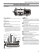
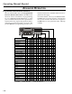
Operating Manual Reprint CONTROLS & CONNECTORS Front Panel de c h f g POWER j k l i POWER Button Press the button to turn the transceiver ON and OFF. TX Indicator This lamp glows red when the radio is transmitting. BUSY Indicator This lamp glows green when the channel is busy. S/T T Button Pressing these buttons changes the current group (and displayed group number or name). Holding this button for more than 1/2 second causes the function to repeat.
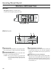
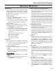
Operating Manual Reprint CONTROLS & CONNECTORS Side Panel Microphone Jack (It is on both sides.) Connect the microphone plug to this jack. Microphone Jack REAR (Heatsink) c d e f Antenna Socket 13.8-V DC Power Connector The 50-ohm coaxial feedline to the antenna must be connected here, using a type-M (PL-259) plug. The supplied DC power cable must be connected to this 4-pin connector. Use only the supplied fused cable, extended if necessary, for power connection.
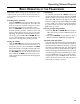
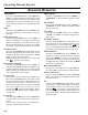
Operating Manual Reprint BASIC OPERATION OF THE TRANSCEIVER Important! - Before turning on the radio the first time, confirm that the power connections have been made correctly and that a proper antenna is connected to the antenna jack. Switching Power ON/OFF Push the POWER switch turn on the radio. The display will become illuminated. The radio will start up on the last channel used prior to shutdown during the previous operating session.
Operating Manual Reprint ADVANCED OPERATION Programmable Function Button (PF button) The VX-5500 includes the seven Programmable Function Buttons (PF button). The PF button functions can be customized, via programming by your VERTEX STANDARD dealer, to meet your communications/network requirements. Some features may require the purchase and installation of optional internal accessories.
Operating Manual Reprint ADVANCED OPERATION Channel Scan The Scanning feature is used to monitor multiple signals programmed into the transceiver. While scanning, the transceiver will check each channel for the presence of a signal, and will stop on a channel if a signal is present. To activate scanning: P Press the assigned PF button of the “Scan” momentarily to activate scanning.
Operating Manual Reprint ADVANCED OPERATION Alpha Numeric Press the assigned PF button of the “Alpha Numeric” to switch the display between the Group/ Channel number, and the Group/Channel name (alphanumeric). A tone will sound each time you switch between numerical and alphanumerical display. GRP UP/DWN Press the assigned PF button of the “GRP UP” or “GRP DWN” to select a different group of channels.
ADVANCED OPERATION SQL (Squelch Level) You can manually adjust the squelch level using this function: 1. Press the assigned PF button of the “SQL”. A tone sounds and SQL appears on the display with the current squelch level. 2. Rotate the CHANNEL selector knob to select the desired level. 3. Press the this key. A tone sounds and the display returns to the normal channel.
Operating Manual Reprint OPTIONAL ACCESSORIES MH-25B7A MH-53C7A MH-53A7A MH-53B7A CE49 CT-70 CT-71 CT-72 CT-93 CT-81 CT-82 CT-83 CNT-6000 RF DECK RMK-4000SH RMK-4000DH RMK-4000DB RMK-4000DBH F2D-8 F5D-14 VTP-50 FVP-25 FVP-35 MDC1200 FP-1023 MLS-200 MLS-100 MMB-75 MMB-76 FIF-7A CN-6 LF-1 1-8 Microphone Heavy Duty Microphone Heavy Duty Microphone w/Noise Canceler Heavy Duty DTMF Microphone w/Noise Canceler Programming Software Radio Programming Cable (Requires VPL-1) Radio to PC Programming Cable Radio to
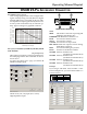
Operating Manual Reprint DSUB 25-PIN ACCESSORY CONNECTOR DSUB25 output level (V) Pin 1: RSSI [Analog Output] A DC voltage proportional to the strength of the signal currently being received (Receiver Signal Strength Indicator) is provided on this pin. This low impedance output is generated by the receiver IF sub-system and buffered by an internal opamp. Typical voltages are graphed as follows: 5.0 4.5 4.0 3.5 3.0 2.5 2.0 1.5 1.0 0.5 0 1259 398 125 398 12.5 DSUB 25-Pin Numbering None MON 4 1.25 0.4 0.
Operating Manual Reprint DSUB 25-PIN ACCESSORY CONNECTOR Similarly, if you assign “CH SW0,” “CH SW1,” and “CH SW2” to the Universal Input Port, you can recall Channels 1~7 as shown below: Channel 1 2 3 4 5 6 7 CH SW0 1 0 1 0 1 0 1 CH SW1 0 1 1 0 0 1 1 CH SW2 0 0 0 1 1 1 1 PINS 2, 3, 4, 6 Sample Circuit If you need to recall all memory channels (15 CH) from the External Controller via the Uni-versal Input Port, you should assign the “All Channel Recall” Command (CH SW 0 ~ CH SW 3) to the Universal Inp
Operating Manual Reprint DSUB 25-PIN ACCESSORY CONNECTOR Pin 13: TXDI [Digital Input for DATA Communications] P TX Hi-speed Data Input Type (jumper JP2005). Input level 800 mV/600 Ohms, Max.input 1.2V P Tx Low-speed Data input Type ( Jumper JP2006). Input level 40 mV/600-Ohms If the Jumper setting is “Low-speed Data” (JP2006 jumpered), this port is usable in the AUDIO (300~3000 Hz) range.
Operating Manual Reprint Note: 1-12
Cloning The VX-5500 includes a convenient “Clone” feature, which allows the programming data from one transceiver to be transferred to another VX-5500. Here is the procedure for Cloning one radio's data to another. Note: When a cloning isn't made, you correct the following part using "CE49." When a "Radio to Radio Clone" which is in the "Miscellaneous" menu is "Disabled," change this menu to "Enabled." 1. 2. 3. 4. Turn both transceivers off.
Specifications GENERAL Number of Channels: Frequency Range: Channel Spacing: Power Supply Voltage: Current Consumption: Ambient Temperature Range: Frequency Stability: RF Input-Output Impedance: Audio Output Impedance: Dimensions: Weight (Approx.): RECEIVER 250 channels 37 - 50 MHz 5 / 10 / 12.5 / 15/ 20 / 25 / 50 kHz 13.8V DC ±15 % Standby: 600 mA Receive: 2.2 A Transmit: 13 A (High) –22°F to +140°F (–30°C to +60°C) Better than ±5 ppm 50 Ohms 4 Ohms 7" (w) x 2.4" (H)x 7.7" (D) (178 x 60 x 195 mm) 4.
REF. 1 2 3 4 5 6 7 8 9 10 Screw List Description BINDING HEAD SCREW M3x6B BINDING HEAD SCREW M3x6NI TAPTITE SCREW M3x8NI TAPTITE SCREW M2.6x6 BINDING HEAD SCREW M3x8NI TAPTITE SCREW M2.6x8 BINDING HEAD SCREW M3x5B FLAT HEAD SCREW M2.6x5B OVAL HEAD SCREW M3x6B SCREW JFS-4S-B1MW VXSTD P/N U20306007 U20306002 U24308002 U23206001 U20308002 U24208001 U20305007 U32450007 U31306007 S5000182 Exploded View & Miscellaneous Parts Qty.
Block Diagram 3-2
Block Diagram 3-3
Interconnection Diagram 3-4
Circuit Description Reception and transmission are switched by “RX” and “TX” lines from the microprocessor unit (MPU). Signal Path Overview The receiver uses double-conversion superheterodyne circuitry, with a 17.7 MHz 1st IF and 450 kHz 2nd IF. The 1st LO, produced by a PLL synthesizer, yields the 17.7 MHz 1st IF. The 2nd LO uses a 17.25 MHz (17.7 MHz-450 kHz) signal generated by a crystal oscillator.
Circuit Description Transmitter DCS Demodulator Voice audio from the microphone is delivered via the Mic (Jack) Unit to the MAIN Unit, after passing through amplifier Q3039, Q2041 (NJM2902V), a preemphasis network, a limiter (IDC: instantaneous deviation control) , and LPF Q2001 (NJM2902V); it then is adjusted for optimum deviation level, and delivered to the next stage.
Alignment The VX-5500 has been carefully aligned at the factory for the specified performance across the frequency range specified for each version. Realignment should therefore not be necessary except in the event of a component failure, or when altering the transceiver version. If a sudden problem occurs during normal operation, it is likely due to component failure; realignment should not be done until after the faulty component has been replaced.
Alignment Before beginning, connect the transceiver and PC using the CT-71 programming cable, and download the EEPROM data from the transceiver to the computer. Store this data in a disk file so that it can be saved and retrieved later. Using the table below, program the channel, CTCSS, and DCS alignment settings for your transceiver version. Upload this file to the transceiver. Note: Signal levels in dB referred to in this procedure are based on 0 dBµ = 0.5 µV (closed circuit).
Alignment Transmitter Output Power The following transmitter parameters can be adjusted from the computer by utilizing the Alignment Software. Refer to the onboard help of the Alignment Software Manual for details. U Select the high band edge frequency channel (CH4), and select the “high” power output level. Key the transmitter and adjust “TX PWR Hi“ for a power output of 70 Watts (± 2.0 W) as indicated on the wattmeter.
Alignment Transmitter Deviation Receiver The following modulation parameters can be adjusted from the computer by utilizing the Alignment Software. Refer to the onboard help of the Alignment Software Manual for details. The sensitivity parameters can be adjusted from the computer by utilizing the Alignment Software. Refer to the onboard help of the Alignment Software Manual for details. U Set up the test equipment as shown for receiver alignment, and install the audio test adapter.
Alignment Squelch Threshold The squelch parameters can also be adjusted from the computer by utilizing the Alignment Software. Refer to the onboard help of the Alignment Software Manual for details. Tight SQL RSSI LEVEL U Select the band center frequency channel (CH3), and with the RF signal generator turned to the same frequency, set the generator for ±3.0 kHz deviation with 1 kHz tone modulation, and set the output level for 12.0 dBµ at the antenna jack.
Alignment Note: 5-6
MAIN Unit 0V (5.6V) (5.6V) Circuit Diagram 3.4V (1.1V) 0.7V~6.5V 4.4V 8.7V 0.9V 7.7V (7.9V) (0.64V) +8 dBm (+12 dBm) (1.6V) (8.8V) 2.5V (2.5V) 5.0V (5.0V) 0 dBm 5.6V (2.4V) 8.1V (8.1V) 8.7V (0V) 3.9V (3.9V) 8.9V (8.9V) 1.7V (1.7V) 2.0V (2.0V) 4.5V (4.5V) 4.2V (3.8V) LOCK:4.9V 0V (8.8V) 0V (8.7V) 4.0V (4.0V) 0V (4.3V) NB on:5.0V NB off:(0V) -116 dBm (4.8V) 0V 0V (0.9V) 0V (4.7V) (2.2V) 0V (3.5V) (0.03V) (2.0V) -114 dBm 0V (5.0V) XX : TX 43.5 MHz, MIC Input Level 1 kHz 3.
MAIN Unit 11.7V (12.5V) 5.0V (5.0V) (1.1V) 1.0V (1.0V) 13.0V (13.8V) 4.0V 4.0V 0.4V (0.4V) 5.0V (5.0V) 5.0V (5.0V) (1.1V) (1.0V) 3.9V (3.9V) (4.0V) (3.8V) 2.2V (2.2V) (3.8V) (1.2V) 4.2V (4.2V) 3.9V (3.9V) 3.9V (3.9V) Power on:0V Power off:13.8V 4.5V (4.5V) 4.5V (4.5V) 2.4V (2.4V) 4.8V (4.8V) 0.6V (5.0V) 4.6V (4.6V) 3.9V (3.9V) ON:5.0V OFF:0V 3.9V (3.9V) 4.0V (4.0V) 4.0V (4.0V) 5.0V (5.0V) 4.0V (4.0V) 3.9V (3.9V) (6.5V) (6.6V) 1 2 3 4 5 6 7 8 (6.6V) (6.6V) 6A-2 XX : TX 43.
MAIN Unit Parts Layout A B C D E F G MB90F583B (Q2025) CXA1846N (Q2019) BU4066BF (Q2007) 1 AT24C256 (Q2036) 2 SPM5001 (Q1040) 3 2SC4154E (LE) (Q1033, 2024) 2SC4226 (R24) (Q1016) 2SC5107-O (MFO) (Q1021) 4 5 RT1N241M (N2) (Q1022, 1043, 2005, 2008, 2009, 2010, 2014, 2015, 2032, 2033, 2037, 2039) TC4W53FU (Q2004) GN010100RL (5A) (Q1006) SD1405 (Q1001) TDA7240AV (Q2018) 2SK3074 (WA) (Q1004) NJM78L05UA (8C) (Q1036) 2SB1132R (BA) (Q1010) TA75S01F(SA) (Q2046) IMH6 (H6) (Q1008, 1020) IMD
MAIN Unit a b c d e f g SA7025DK (Q1029) MX165CDW (Q2017) TA31136FN (Q1034) 1 2SB1201STP (Q1005) NJM2904V (Q2042) NJM2902V (Q1038, 2001, 2003, 2040, 2041, 2047) 2SC1972 (Q1002) TC4W53FU (Q1041) 2 BU4053BCF (Q2026) LA8630M (Q2031) 2SC4154E (LE) (Q1007, 10012, 1014) 2SC3356 (R24) (Q1039) 2SC4215Y (QY) (Q1023, 1035) IMH6 (H6) (Q2011) 2SB1132Q (BA) (Q1009) MM1216ENRE (1A) (Q1003) 2SK508 (K52) (Q1031, 1032) 2SK2035 (KP) (Q1019) 3 4 2SC5415E (EA) (Q1027) 2SJ327Z (Q2027) IMX1 (X1) (Q2006)
MAIN Unit Parts List REF. DESCRIPTION C 1001 C 1002 C 1003 C 1004 C 1005 C 1006 C 1007 C 1008 C 1009 C 1011 C 1012 C 1013 C 1014 C 1015 C 1017 C 1018 C 1019 C 1020 C 1021 C 1023 C 1024 C 1025 C 1026 C 1027 C 1028 C 1029 C 1030 C 1031 C 1033 C 1034 C 1035 C 1036 C 1037 C 1038 C 1039 C 1040 C 1041 C 1042 C 1043 C 1044 C 1045 C 1046 C 1047 C 1048 C 1049 C 1050 C 1051 C 1052 C 1053 C 1054 C 1055 C 1056 C 1057 C 1058 C 1059 C 1060 C 1061 C 1062 PCB with Components Printed Circuit Board CHIP CAP. CHIP CAP.
MAIN Unit REF. C 1063 C 1063 C 1064 C 1065 C 1067 C 1068 C 1070 C 1071 C 1072 C 1073 C 1074 C 1075 C 1078 C 1079 C 1080 C 1081 C 1083 C 1084 C 1085 C 1086 C 1087 C 1088 C 1089 C 1090 C 1091 C 1092 C 1093 C 1094 C 1095 C 1096 C 1098 C 1099 C 1100 C 1101 C 1102 C 1103 C 1104 C 1105 C 1106 C 1107 C 1108 C 1109 C 1110 C 1111 C 1112 C 1113 C 1114 C 1115 C 1116 C 1118 C 1119 C 1120 C 1121 C 1122 C 1123 C 1124 C 1125 C 1127 C 1128 C 1129 C 1130 6A-6 DESCRIPTION FILM CAP. FILM CAP. CHIP CAP. CHIP CAP. CHIP CAP.
MAIN Unit REF. C 1132 C 1133 C 1134 C 1135 C 1137 C 1138 C 1139 C 1140 C 1141 C 1142 C 1143 C 1144 C 1145 C 1146 C 1147 C 1148 C 1149 C 1150 C 1151 C 1152 C 1153 C 1156 C 1157 C 1158 C 1159 C 1160 C 1161 C 1162 C 1163 C 1164 C 1165 C 1166 C 1167 C 1168 C 1169 C 1170 C 1171 C 1172 C 1173 C 1174 C 1175 C 1176 C 1177 C 1178 C 1179 C 1180 C 1181 C 1182 C 1183 C 1184 C 1185 C 1186 C 1187 C 1188 C 1189 C 1190 C 1191 C 1192 C 1193 C 1194 C 1196 DESCRIPTION CHIP CAP. CHIP CAP. CHIP CAP. CHIP CAP. CHIP CAP.
MAIN Unit REF. C 1197 C 1198 C 1199 C 1200 C 1201 C 1202 C 1203 C 1205 C 1206 C 1207 C 1208 C 1209 C 1210 C 1211 C 1212 C 1214 C 1215 C 1216 C 1217 C 1218 C 1219 C 1220 C 1221 C 1222 C 1223 C 1224 C 1225 C 1226 C 1227 C 1228 C 1229 C 1230 C 1231 C 1232 C 1233 C 1234 C 1234 C 1235 C 1236 C 1237 C 1238 C 1239 C 1240 C 1241 C 1242 C 1243 C 1244 C 1245 C 1247 C 1248 C 1249 C 1250 C 1251 C 1252 C 1253 C 1255 C 1256 C 1257 C 1258 C 1259 C 1260 6A-8 DESCRIPTION CHIP CAP. CHIP CAP. CHIP CAP. CHIP CAP. CHIP CAP.
MAIN Unit REF. C 1262 C 1263 C 1264 C 1265 C 1266 C 1267 C 1268 C 1269 C 1270 C 1271 C 1272 C 1273 C 1274 C 1275 C 1276 C 1277 C 1278 C 1279 C 1280 C 1281 C 1282 C 1283 C 1284 C 1285 C 1287 C 1288 C 2001 C 2002 C 2003 C 2004 C 2005 C 2006 C 2007 C 2008 C 2009 C 2010 C 2011 C 2013 C 2014 C 2015 C 2016 C 2017 C 2018 C 2019 C 2020 C 2021 C 2022 C 2023 C 2024 C 2025 C 2026 C 2027 C 2028 C 2029 C 2030 C 2031 C 2032 C 2033 C 2034 C 2035 C 2036 DESCRIPTION CHIP CAP. CHIP CAP. CHIP TA.CAP. CHIP CAP. CHIP CAP.
MAIN Unit REF. C 2037 C 2038 C 2039 C 2040 C 2041 C 2042 C 2043 C 2044 C 2045 C 2046 C 2047 C 2049 C 2051 C 2052 C 2054 C 2057 C 2058 C 2059 C 2060 C 2061 C 2062 C 2063 C 2064 C 2065 C 2066 C 2067 C 2068 C 2069 C 2070 C 2071 C 2072 C 2073 C 2074 C 2075 C 2076 C 2078 C 2079 C 2080 C 2081 C 2082 C 2083 C 2084 C 2085 C 2086 C 2087 C 2088 C 2089 C 2090 C 2092 C 2093 C 2094 C 2095 C 2097 C 2098 C 2099 C 2100 C 2101 C 2102 C 2103 C 2104 C 2105 6A-10 DESCRIPTION CHIP CAP. CHIP CAP. CHIP CAP. CHIP CAP. CHIP CAP.
MAIN Unit REF. C 2106 C 2107 C 2108 C 2109 C 2110 C 2111 C 2112 C 2113 C 2114 C 2115 C 2116 C 2117 C 2118 C 2119 C 2120 C 2121 C 2122 C 2123 C 2124 C 2125 C 2126 C 2127 C 2128 C 2129 C 2130 C 2131 C 2132 C 2133 C 2134 C 2135 C 2136 C 2137 C 2138 C 2139 C 2140 C 2141 C 2142 C 2143 C 2144 C 2145 C 2146 C 2147 C 2148 C 2149 C 2150 C 2151 C 2153 C 2155 C 2156 C 2157 C 2158 C 2159 C 2160 C 2162 C 2163 C 2164 C 2165 C 2166 C 2167 C 2168 C 2169 DESCRIPTION CHIP CAP. CHIP CAP. CHIP CAP. CHIP CAP. CHIP TA.CAP.
MAIN Unit REF. DESCRIPTION C 2170 CHIP TA.CAP. C 2171 CHIP CAP. C 2172 CHIP TA.CAP. C 2173 CHIP CAP. C 2174 CHIP CAP. C 2176 CHIP CAP. C 2177 CHIP CAP. C 2178 CHIP CAP. C 2179 CHIP CAP. C 2180 CHIP CAP. C 2181 CHIP CAP. C 2182 CHIP CAP. C 2223 CHIP TA.CAP. C 2226 CHIP CAP. C 2227 CHIP CAP. C 2228 CHIP CAP. C 2230 CHIP CAP. C 2231 CHIP CAP. C 2232 CHIP CAP. C 2233 CHIP CAP. C 2251 CHIP TA.CAP. C 2253 CHIP TA.CAP. C 2255 CHIP CAP. C 2256 CHIP CAP. C 2257 CHIP CAP. C 2258 CHIP CAP. C 2259 CHIP CAP.
MAIN Unit REF.
MAIN Unit REF. L 1026 L 1027 L 1028 L 1029 L 1030 L 1031 L 1032 L 1033 L 1035 L 1036 L 1037 L 1038 L 1039 L 1040 L 1041 L 1042 L 1043 L 1082 L 1083 L 1084 L 1085 L 1086 L 2001 P 1001 Q 1001 Q 1002 Q 1003 Q 1004 Q 1005 Q 1006 Q 1007 Q 1008 Q 1009 Q 1010 Q 1011 Q 1012 Q 1014 Q 1015 Q 1016 Q 1017 Q 1018 Q 1019 Q 1020 Q 1021 Q 1022 Q 1023 Q 1025 Q 1026 Q 1027 Q 1029 Q 1030 Q 1031 Q 1032 Q 1033 Q 1034 Q 1035 Q 1036 Q 1038 Q 1039 Q 1040 Q 1041 6A-14 DESCRIPTION COIL A2 CHIP COIL M.RFC M.RFC CHIP COIL M.
MAIN Unit REF.
MAIN Unit REF. R 1026 R 1027 R 1028 R 1029 R 1030 R 1031 R 1032 R 1033 R 1034 R 1035 R 1036 R 1037 R 1038 R 1039 R 1040 R 1041 R 1042 R 1043 R 1044 R 1045 R 1046 R 1047 R 1048 R 1050 R 1051 R 1052 R 1053 R 1054 R 1055 R 1056 R 1057 R 1058 R 1059 R 1060 R 1061 R 1062 R 1063 R 1064 R 1065 R 1066 R 1067 R 1068 R 1069 R 1070 R 1071 R 1072 R 1073 R 1074 R 1075 R 1076 R 1077 R 1078 R 1079 R 1080 R 1081 R 1082 R 1083 R 1084 R 1086 R 1087 R 1088 6A-16 DESCRIPTION CHIP RES. CHIP RES. CHIP RES. CHIP RES. CHIP RES.
MAIN Unit REF. R 1089 R 1090 R 1091 R 1092 R 1093 R 1094 R 1095 R 1096 R 1097 R 1098 R 1099 R 1099 R 1100 R 1101 R 1101 R 1102 R 1103 R 1103 R 1104 R 1107 R 1111 R 1114 R 1115 R 1121 R 1124 R 1126 R 1128 R 1131 R 1132 R 1133 R 1134 R 1135 R 1136 R 1137 R 1138 R 1139 R 1140 R 1141 R 1142 R 1143 R 1144 R 1145 R 1146 R 1147 R 1148 R 1149 R 1150 R 1152 R 1153 R 1154 R 1157 R 1158 R 1159 R 1160 R 1162 R 1163 R 1164 R 1165 R 1166 R 1167 R 1168 DESCRIPTION CHIP RES. CHIP RES. CHIP RES. CHIP RES. CHIP RES.
MAIN Unit REF. R 1170 R 1172 R 1173 R 1174 R 1178 R 1180 R 1181 R 1182 R 1183 R 1185 R 1186 R 1187 R 1191 R 1192 R 1194 R 1195 R 1196 R 1197 R 1198 R 1200 R 2001 R 2002 R 2003 R 2004 R 2005 R 2006 R 2007 R 2008 R 2009 R 2010 R 2011 R 2012 R 2013 R 2014 R 2015 R 2016 R 2017 R 2018 R 2019 R 2020 R 2021 R 2022 R 2023 R 2024 R 2025 R 2026 R 2027 R 2028 R 2029 R 2030 R 2031 R 2032 R 2033 R 2034 R 2035 R 2037 R 2039 R 2040 R 2041 R 2042 R 2043 6A-18 DESCRIPTION CHIP RES. CHIP RES. CHIP RES. CHIP RES. CHIP RES.
MAIN Unit REF. R 2044 R 2045 R 2046 R 2047 R 2048 R 2049 R 2050 R 2051 R 2052 R 2053 R 2054 R 2055 R 2056 R 2057 R 2058 R 2059 R 2060 R 2061 R 2062 R 2063 R 2064 R 2065 R 2066 R 2067 R 2068 R 2069 R 2070 R 2071 R 2072 R 2073 R 2074 R 2075 R 2076 R 2077 R 2078 R 2079 R 2080 R 2081 R 2082 R 2083 R 2084 R 2085 R 2086 R 2087 R 2088 R 2089 R 2092 R 2093 R 2094 R 2095 R 2096 R 2097 R 2098 R 2099 R 2100 R 2101 R 2103 R 2104 R 2105 R 2106 R 2107 DESCRIPTION CHIP RES. CHIP RES. CHIP RES. CHIP RES. CHIP RES.
MAIN Unit REF. R 2108 R 2110 R 2111 R 2112 R 2113 R 2114 R 2115 R 2116 R 2117 R 2118 R 2119 R 2120 R 2121 R 2122 R 2123 R 2124 R 2125 R 2126 R 2127 R 2128 R 2131 R 2132 R 2133 R 2134 R 2136 R 2137 R 2138 R 2139 R 2140 R 2141 R 2142 R 2143 R 2144 R 2145 R 2146 R 2147 R 2148 R 2149 R 2150 R 2151 R 2152 R 2153 R 2154 R 2155 R 2156 R 2157 R 2158 R 2159 R 2160 R 2161 R 2162 R 2163 R 2164 R 2165 R 2166 R 2167 R 2168 R 2169 R 2170 R 2171 R 2172 6A-20 DESCRIPTION CHIP RES. CHIP RES. CHIP RES. CHIP RES. CHIP RES.
MAIN Unit REF. R 2173 R 2174 R 2175 R 2176 R 2177 R 2178 R 2179 R 2180 R 2181 R 2182 R 2183 R 2185 R 2186 R 2187 R 2188 R 2189 R 2190 R 2191 R 2192 R 2193 R 2194 R 2195 R 2196 R 2197 R 2198 R 2199 R 2200 R 2201 R 2202 R 2203 R 2204 R 2205 R 2206 R 2207 R 2208 R 2210 R 2212 R 2214 R 2215 R 2216 R 2217 R 2218 R 2219 R 2220 R 2221 R 2222 R 2224 R 2225 R 2226 R 2228 R 2229 R 2231 R 2232 R 2233 R 2234 R 2235 R 2236 R 2252 R 2255 R 2266 R 2267 DESCRIPTION CHIP RES. CHIP RES. CHIP RES. CHIP RES. CHIP RES.
MAIN Unit REF. R 2270 R 2271 R 2273 R 2274 R 2278 R 2280 R 2281 R 2282 R 2283 R 2285 R 2286 R 2287 R 2288 R 2289 R 2290 R 2291 R 2292 R 2293 R 2294 R 2295 R 2296 T 1001 T 1002 T 1003 T 1004 T 1005 T 1006 T 1007 T 1008 T 1009 T 1010 T 1011 TC1001 TH1001 TH1002 TH2001 X 1001 X 2001 XF1001 XF1001 XF1002 XF1002 6A-22 DESCRIPTION CHIP RES. CHIP RES. CHIP RES. CHIP RES. CHIP RES. CHIP RES. CHIP RES. CHIP RES. CHIP RES. CHIP RES. CHIP RES. CHIP RES. CHIP RES. CHIP RES. CHIP RES. CHIP RES. CHIP RES. CHIP RES.
Circuit Diagram DISPLAY Unit 6B-1
DISPLAY Unit Note: 6B-2
DISPLAY Unit Parts Layout A B C D E F 1 2 3 Side A S-93C46AMFN-TB (Q3012) 2SB1132Q (BA) (Q3031) DTC323TK (H02) (Q3003) NJM78L05UA (8C) (Q3021) MC2848 (A6) (D3008) DAP202U (P) (D3006) MC2850 (A7) (D3018, 3019) 6B-3
DISPLAY Unit Parts Layout a b c e d g f 1 2 3 Side B NJM2902V (Q3039) HD64F3642AH (Q3014) DTC323TK (H02) (Q3008, 3009) IMD3 (D3) (Q3013) TC4S66F (C9) (Q3043) IMH6 (H6) (Q3015, 3033) IMZ1 (Z1) (Q3004, 3011, 3040) IMX1 (X1) (Q3010, 3038) 2SC4154E (LE) (Q3019) RT1N241M (N2) (Q3005, 3020, 3022, 3025, 3026, 3027) 2SB1132Q (BA) (Q3028, 3029) LC75823W (Q3001) 6B-4 2SA1602A (MF) (Q3017, 3401) UMW1 (W1) (Q3030) RN5VL35AA (C5) (Q3016) 1SS226 (C3) (D3005)
DISPLAY Unit Parts List REF. DESCRIPTION VALUE WV TOL. MFR’S DESIG VXSTD P/N VERS. LOT. SIDE. LAY ADR.
DISPLAY Unit REF. C 3065 C 3069 C 3070 C 3071 C 3074 C 3075 C 3076 C 3079 C 3091 C 3092 C 3093 C 3094 C 3095 C 3096 D 3005 D 3006 D 3008 D 3010 D 3011 D 3012 D 3013 D 3015 D 3016 D 3017 D 3018 D 3019 D 3020 D 3021 D 3022 D 3023 DS3002 DS3002 J 3001 J 3005 J 3007 J 3008 J 3009 L 3001 Q 3001 Q 3003 Q 3004 Q 3005 Q 3008 Q 3009 Q 3010 Q 3011 Q 3012 Q 3013 Q 3014 Q 3015 Q 3016 Q 3017 Q 3019 Q 3020 Q 3021 Q 3022 Q 3025 Q 3026 Q 3027 Q 3028 6B-6 DESCRIPTION VALUE CHIP CAP. AL.ELECTRO.CAP. AL.ELECTRO.CAP.
DISPLAY Unit REF.
DISPLAY Unit REF. R 3060 R 3061 R 3061 R 3062 R 3062 R 3063 R 3064 R 3065 R 3066 R 3067 R 3068 R 3069 R 3070 R 3071 R 3072 R 3073 R 3074 R 3075 R 3076 R 3077 R 3078 R 3079 R 3080 R 3081 R 3082 R 3083 R 3084 R 3085 R 3086 R 3087 R 3088 R 3089 R 3090 R 3092 R 3093 R 3095 R 3096 R 3096 R 3097 R 3097 R 3099 R 3103 R 3104 R 3105 R 3106 R 3107 R 3108 R 3109 R 3110 R 3111 R 3112 R 3113 R 3114 R 3115 R 3116 R 3117 R 3118 R 3119 R 3120 R 3121 6B-8 DESCRIPTION CHIP RES. CHIP RES. CHIP RES. CHIP RES. CHIP RES.
DISPLAY Unit REF. DESCRIPTION R 3122 R 3123 R 3124 R 3125 R 3126 R 3127 R 3128 R 3129 R 3135 R 3136 R 3137 R 3142 R 3143 R 3143 R 3144 R 3145 R 3146 R 3147 R 3150 R 3152 R 3153 R 3154 R 3155 R 3156 R 3157 R 3158 R 3159 R 3160 R 3161 R 3162 R 3162 R 3164 R 3166 R 3167 R 3168 S 3007 S 3008 S 3009 X 3001 CHIP RES. CHIP RES. CHIP RES. CHIP RES. CHIP RES. CHIP RES. CHIP RES. CHIP RES. CHIP RES. CHIP RES. CHIP RES. CHIP RES. CHIP RES. CHIP RES. CHIP RES. CHIP RES. CHIP RES. CHIP RES. CHIP RES. CHIP RES.
DISPLAY Unit Note: 6B-10
KEY Unit Circuit Diagram 1.96V 5.8V 3.9V 1.92V 3.82V 4.62V 7.71V 4.95V 3.18V 3.87V 4.19V 4.34V 4.46V 4.53V 4.
KEY Unit Note: 6C-2
KEY Unit Parts List REF. DESCRIPTION VALUE WV TOL. MFR’S DESIG VXSTD P/N VERS. LOT. SIDE. LAY ADR. *** KEY UNIT *** PCB with Components Printed Circuit Board C 3402 CHIP CAP. D 3401 LED D 3402 LED D 3403 LED D 3404 LED D 3405 LED J 3401 CONNECTOR MC3401 MIC. ELEMENT Q 3401 TRANSISTOR R 3401 CHIP RES. R 3402 CHIP RES. R 3403 CHIP RES. R 3404 CHIP RES. R 3405 CHIP RES. R 3406 CHIP RES. R 3407 CHIP RES. R 3408 CHIP RES. R 3409 CHIP RES. R 3410 CHIP RES. R 3411 CHIP RES. R 3412 CHIP RES.
KEY Unit Note: 6C-4
VR Unit Circuit Diagram Side A C3603 R3604 VR3601 R3605 C 3602 R3607 C3605 S3601 C3601 R3606 J3601 R3602 R3603 C3604 R3601 Parts Layout C3606 Side B Parts List REF. DESCRIPTION VALUE WV TOL. MFR’S DESIG VXSTD P/N VERS. LOT. SIDE. LAY ADR. *** VR UNIT *** C 3601 C 3602 C 3603 C 3604 C 3605 C 3606 J 3601 R 3601 R 3602 R 3603 R 3604 R 3605 R 3606 R 3607 S 3601 VR3601 PCB with Components Printed Circuit Board CHIP CAP. CHIP CAP. CHIP CAP. CHIP CAP. CHIP CAP. CHIP CAP.
MIC CONN Unit Circuit Diagram Parts Layout Side A Side B Parts List REF. DESCRIPTION VALUE WV TOL. MFR’S DESIG VXSTD P/N VERS. LOT. SIDE. LAY ADR.
NB Unit Circuit Diagram 3.8V NB on : 8.7V NB off : 0V 2.8V 8.2V 2.6V 2.8V 8.5V 2.1V 2.4V 4.3V 7.9V 0.6V 5.1V 8.7V 3.9V 0V 8.7V 0V 6.0V 0.6V 0V 1.1V 0.
NB Unit Parts List REF. DESCRIPTION C 6801 C 6802 C 6803 C 6804 C 6805 C 6806 C 6807 C 6808 C 6809 C 6810 C 6811 C 6812 C 6813 C 6814 C 6815 C 6816 C 6817 C 6818 C 6819 C 6820 C 6821 C 6822 C 6823 C 6824 C 6825 C 6826 D 6801 L 6801 L 6802 L 6803 L 6804 Q 6801 Q 6802 Q 6803 Q 6804 Q 6805 Q 6806 Q 6807 Q 6808 R 6801 R 6802 R 6803 R 6804 R 6805 R 6806 R 6807 R 6808 R 6809 R 6810 R 6811 R 6812 R 6813 R 6814 R 6815 PCB with Components Printed Circuit Board CHIP TA.CAP. CHIP CAP. CHIP CAP. CHIP CAP. CHIP CAP.
NB Unit REF. R 6816 R 6817 R 6818 R 6819 R 6820 R 6821 R 6822 R 6823 R 6824 R 6825 R 6826 R 6827 R 6828 R 6829 R 6830 R 6831 R 6832 R 6833 DESCRIPTION CHIP RES. CHIP RES. CHIP RES. CHIP RES. CHIP RES. CHIP RES. CHIP RES. CHIP RES. CHIP RES. CHIP RES. CHIP RES. CHIP RES. CHIP RES. CHIP RES. CHIP RES. CHIP RES. CHIP RES. CHIP RES. VALUE 10k 150 10k 1k 100 22k 10k 1k 680k 1k 1k 5.6k 33 56k 100k 5.
NB Unit Note: 6E-4
F2D-8 2-Tone Decode Unit Circuit Diagram Parts Layout Side A TC7S04FU (E5) (Q1003) TA75S01F (SA) (Q1004) Side B HD64F3334YTF16 (Q1001) DTC124TU (05) (Q1005) 7A-1
F2D-8 2-Tone Decode Unit Parts List REF. DESCRIPTION VALUE V/W TOL. MFR’S DESIG VXSTD P/N VERS. LOT. SIDE LAY ADR *** F2D-8 *** C 1001 C 1002 C 1003 C 1007 C 1007 C 1007 C 1008 C 1009 C 1010 C 1011 C 1012 C 1013 C 1014 D 1001 D 1002 J 1001 Q 1001 Q 1003 Q 1004 Q 1005 R 1001 R 1002 R 1003 R 1004 R 1005 R 1006 R 1007 R 1008 R 1009 R 1009 R 1010 R 1015 R 1016 R 1016 R 1017 7A-2 Printed Circuit Board CHIP TA.CAP. CHIP CAP. CHIP CAP. CHIP CAP. CHIP CAP. CHIP CAP. CHIP CAP. CHIP CAP. CHIP CAP.
VTP-50 VX-Trunk Unit Circuit Diagram Parts Layout Side B Side A NJM2904V (Q1001) MC68HSC705C8A502 (Q1002) TA75S01F (SA) (Q1003) BR93LC56FV (Q1004) 7B-1
VTP-50 VX-Trunk Unit Parts List REF. DESCRIPTION VALUE V/W TOL. MFR’S DESIG VXSTD P/N VERS. LOT.
FVP-25 Encryption / DTMF Pager Unit Circuit Diagram Parts Layout Side A M64026FP (Q1001) Side B LC73881 (Q1002) DTC144EU (26) (Q1003) 7C-1
FVP-25 Encryption / DTMF Pager Unit Parts List REF. DESCRIPTION VALUE V/W TOL. MFR’S DESIG VXSTD P/N VERS. LOT. SIDE LAY ADR *** FVP-25 *** Printed Circuit Board C 1001 CHIP CAP. C 1002 CHIP CAP. C 1003 CHIP CAP. C 1004 CHIP CAP. C 1005 CHIP CAP. C 1007 CHIP CAP. C 1007 CHIP CAP. C 1008 CHIP CAP. C 1009 CHIP CAP. C 1010 CHIP CAP. C 1011 CHIP CAP. C 1012 CHIP TA.CAP. C 1013 CHIP CAP. C 1014 CHIP CAP. D 1001 DIODE D 1002 DIODE J 1001 CONNECTOR Q 1001 IC Q 1002 IC Q 1003 TRANSISTOR R 1001 CHIP RES.
F5D-14 5-Tone Unit Circuit Diagram Parts Layout Side A TK71650SC (L50) (Q1001) DTC114TE (04) (Q1002) PIC17LC44-08/PQ (Q1003) Side B 2SC4617 (BR) (Q1004) MD09 (Q1005) BR93LC66FV (Q1006) 7D-1
F5D-14 5-Tone Unit Parts List REF. DESCRIPTION VALUE V/W TOL. MFR’S DESIG VXSTD P/N VERS. LOT.
FIF-7A Connection Unit Circuit Diagram Parts Layout Side A NJM2902V (Q1001) Side B TC7WT125FU (Q1008, 1011, 1012) TK71635SCL (L35) (Q1003) TC7S04FU (E5) (Q1004) 7E-1
FIF-7A Connection Unit Parts List REF. DESCRIPTION VALUE V/W TOL. MFR’S DESIG VXSTD P/N VERS. LOT.
FIF-7A Connection Unit REF. R 1007 R 1008 R 1009 R 1011 R 1012 R 1013 R 1014 R 1015 R 1017 R 1018 R 1019 R 1020 R 1022 R 1023 R 1024 R 1026 R 1028 R 1029 R 1033 R 1034 R 1035 R 1037 R 1038 R 1047 R 1049 R 1050 R 1051 R 1052 R 1053 R 1054 R 1059 R 1060 R 1061 R 1061 R 1062 R 1062 R 1063 R 1064 R 1065 R 1066 R 1067 R 1068 R 1069 R 1069 R 1069 R 1070 R 1071 X 1001 X 1002 X 1002 DESCRIPTION CHIP RES. CHIP RES. CHIP RES. CHIP RES. CHIP RES. CHIP RES. CHIP RES. CHIP RES. CHIP RES. CHIP RES. CHIP RES. CHIP RES.
FIF-7A Connection Unit Note: 7E-4
Copyright © 2005 VERTEX STANDARD CO., LTD. All rights reserved E C 0 3 4 L 9 0 A No portion of this manual may be reproduced without the ermission of VERTEX STANDARD CO., LTD.