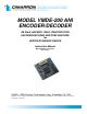
MODEL VMDE-200 ANI ENCODER/DECODER GE Star® AND MDC-1200®, IDENTIFICATION ENCODER/DECODER AND DTMF ENCODER for VERTEX/STANDARD RADIOS Instruction Manual Manual Number 05 30 0020 Rev 101022 © 2005 – 2009 Cimarron Technologies Corp., Escondido, CA, USA. All rights reserved. No part of this manual may be reproduced in any way without the express written permission of Cimarron Technologies Corporation.
MODEL VMDE-200 ANI ENCODER/DECODER for Vertex/Standard Radios © 2005 - 2009Cimarron Technologies Corporation All rights reserved Cimarron Technologies Inc. 934 S. Andreasen Suite G Escondido, CA 92029 USA Voice FAX Email Web : 760-738-3282 : 760-480-0233 : service@cimtechcorp.com : www.cimtechcorp.com Cimarron Technologies Corporation is a licensee of the Motorola MDC-1200 Protocol technology.
ii Contents C H A P T E R 1 FEATURES...........................................................5 What Is the VMDE-200 ..............................................................................................................5 Capabilities ..................................................................................................................................5 Specifications ......................................................................................................................
iii DTMF PTT ID, Emergency ID .......................................................................................... 18 DTMF character duration ................................................................................................... 18 DTMF inter-character duration .......................................................................................... 18 Enable Manual Keypad DTMF ..........................................................................................
iv DTMF Specifics .........................................................................................................................26 Decode ID Display Operations .................................................................................................27 GE Star® ................................................................................................................................ 27 MDC-1200® .........................................................................................
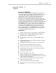
Chapter 1 C H A P T E R Features Features 1 What Is the VMDE-200 The Cimarron Technologies Model VMDE-200 is a plug-in ANI encoder/decoder module capable of PTT ANI and Emergency ANI in GE Star®, MDC-1200® or DTMF signaling format in Vertex communications radios. The unit provides Automatic Numeric Identification of a specific radio transmitter each time the microphone press-to-talk (PTT) switch is activated.
6 Chapter 1 Features Automatic man-down alarm reporting with unique coding for GE Star® and DTMF Status and canned messages can be programmed instead of the emergency and man-down reporting Decodes and displays the ANI of the person transmitting Receiver data mute MDC-1200® message adaptability enhances compatibility with existing unique systems
Chapter 1 Features Specifications Data Format Modulation Type Rate GE Star® PSK (Phase Shift Key) FSK DTMF 400 bps on 1600hz carrier 1200 bps, 1200/1800 Hz ID Range Aliasing ID Locations Messages 0001 to 16,383 0001-DEEE 254 entries maximum 254 entries maximum ANI at Beginning, End or Both PTT ANI, Emergency, PTT ANI, Emergency. Man-Down, TOT. Man-Down sends Messages can be Emergency. Short Call changed to any Alert, Long Call Alert, allowable GE Star® Voice Select Call, Radio message.
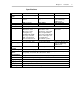
8 Chapter 2 Programming C H A P T E R Programming 2 CE-73 Programming Software The VMDE-200 is programmed while installed in the host radio. This is accomplished by placing the host radio into sub-clone mode and then attaching the appropriate programming cable and opening the CE-73 software. The radio must be in sub-clone mode before attempting upload or download. Refer to the following table for radio specifics: Radio Model Programming Software Firmware Version VX-410/420 CE-64 Ver 1.10 1.
Chapter 2 Programming 9
10 Chapter 2 Programming
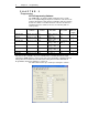
Chapter 2 Programming 11 If the ―Unit ID per Channel‖ box is checked, you will be able to click ―Unit ID‖ in the menu bar and designate a different ANI ID on a per-channel basis. Only select radios support the ―Per Channel ID‖ Feature. Contact Vertex/Standard for a list of supporting radios. If Unit ID per channel is checked, and the radio is placed on a channel where no ID is specified in the Unit ID/Channel table, then the ID listed under ―Common‖ is used.
12 Chapter 2 Programming Uploading and Downloading Uploading transfers information from the VMDE-200 to the CE-73 programming software. Downloading transfers information from the CE-73 programming software into the VMDE-200. The software permits you to select which data you desire to transfer. ―Parameters‖ transfers only the ―Programmable Parameters‖ and does not deal with the alias tables. ―All‖ will transfer the programmable parameters and both alias tables.
Chapter 2 Programming 13 Once you select a format, the edit window appears as shown below. Note that there is a selection for 8 digit or 10 digit display types. Portable radios can handle 8 digit display lengths, while most mobiles allow 10 digit lengths. To enter a new alias, press the ADD button. Enter the appropriate Alias and the associated ID and press OK. The new entry is added to the list.
14 Chapter 2 Programming Continue until all entries have been made. The display can be sorted by (ID) or (Alias) to facilitate management. Programmable Parameters The following parameters are programmable using the Vertex/Standard supplied CE-73 programming software. Default values are italicized in brackets to the right of the parameter. Main Menu Attack Delay (N/A for end send) 0ms to 1000ms in steps of 50ms. [Default 300mS] PTT ANI repeat timer (time since last PTT press.
Chapter 2 Programming 15 PTT ID (1 – 16383) [Default 9999] PTT Message value (0x00-0x7F) [Default 0x01] TOT ID (1 – 16383) [Default 9999] TOT Message value (0x00-0x7F) [Default 0x09] Emergency ID (1 – 16383) [Default 9999] Emergency Message value (0x00-0x7F) [Default 0x07] Man Down ID (1 – 16383) [Default 9999] Man Down Message value (0x00-0x7F) [Default 0x0F] Group ID (0 – 16383) [Default 0] Selective Call to Unmute (Y/N) [Default No] Common – DTMF PTT ID (1 – FFFFFFFF) [Default = 11234] Emergency ID (
16 Chapter 2 Programming PTT ANI repeat timer: Used to reduce the amount of data transmissions. If the selected time since the last PTT press is not exceeded, data is not transmitted with that PTT press. Time out timer: If the radio is held keyed up for greater than the selected time, the ID is transmitted and the radio is automatically unkeyed. Send ID at beginning: If programmed ―Yes‖, the ID will be transmitted when the user keys the radio.
Chapter 2 Programming 17 Emergency TX warning tone: If programmed ―Yes‖, a warning tone will sound through the local speaker to advise the user that an emergency message is being transmitted. Open Microphone Monitor on Emergency TX time If not set to zero, once an emergency is activated, the radio will key up and transmit ambient noise for this period of time. It will then unkey and remain unkeyed for a programmed amount of time and then repeat the process.
18 Chapter 2 Programming number but must not be used as a PTT or Emergency ID on any radio in the system. The default is 0 (zero) which effectively means that there is no group call (only the all call). GE Star® Selective Call to Unmute This is similar to the MDC-1200® Voice Select Call. If this feature is enabled, the radio will remain muted unless a GE Star® Selective Call command is received.
Chapter 2 Programming 19 Man Down Warning Delay Once the VMDE-200 senses a man down situation, this timer begins to run(0 – 255 S). If the radio is not uprighted within this period of time, a warning tone lasting 1 second is sounded. If the radio is uprighted, the warning timer resets. Man Down Activation Delay If the warning delay timer succeeds to complete its countdown and the warning tone is sounded, the activation delay timer begins to run(0 – 255 S).
20 Chapter 3 Operation C H A P T E R Operation 3 Viewing the Programmed ID To review the programmed ID on the channel selected, press the <#> (pound) key. The ID will de displayed for 5 seconds and then the display will return to the channel information presentation. PTT ANI Operation On specified radio channels, with the press of the PTT button, the VMDE-200 disables the radio microphone and then transmits the ANI ID.
Chapter 3 Operation upon receipt of an acknowledgment or by pressing . Cycling power also will terminate the cycle. If the number of repeat transmissions is set to 1 (one), the transmission will be considered non-critical. The radio display will present ―Msg Sent‖ instead of ―Emrgency‖. The message type can be changed to a unique value. Man Down Capabilities The VMDE-200 board contains wire feed-throughs for attaching wires to permit the connection of a man down sensing switch.
22 Chapter 3 Operation emergency is terminated and replaced with the Man Down cycle. The Man Down cycle is terminated at the conclusion of the repeats; upon receipt of an acknowledgment or by pressing . Cycling power also will terminate the cycle. If the number of repeat transmissions is set to 1 (one), the transmission will be considered non-critical. The radio display will present ―Msg Sent‖ instead of ―Man-Down‖. The message type can be changed to a unique value.
Chapter 3 Operation DTMF ANI Typically, in DTMF ANI, the PTT ID and the Emergency ID are different so the base decoder can determine what is an emergency message. Systems using dispatch consoles generally define a DTMF PTT ID as a number beginning with a 1 and DTMF Emergency ID’s begin with a 7. The length of a DTMF character is programmable 25 mS through 1000 mS in 25 mS steps. The pause between DTMF characters is programmable 25 mS through 1000 mS in 25 mS steps.
24 Chapter 3 Operation MDC-1200® Call Alert The VMDE-200 is capable of both ―Long call alert‖ and ―Short call alert‖. The personality programming of the radio permits the selection of which call alert will be used for transmit. In receive, the VMDE-200 will react to either type, but a received short call alert will not have sender ID information. To Send a call alert, press the button until ―ALERT‖ appears in the display then press the button to select the target radio.
Chapter 3 Operation allows the receive audio to pass to the speaker. The display will show alternating between the calling ID (or Alias) and —VSC—. The speaker remains unmuted until loss of carrier. The user may press the PTT and talk without any special button presses. VSC data will be transmitted to open the target radio and communications may proceed. This VSC mode remains in effect to permit continued conversations until the button is pressed.
26 Chapter 3 Operation seconds. The radio will send the appropriate acknowledgment to the requesting radio. If the radio receives a selective call command with an ID that matches the programmed GE Star® group ID (or 00000 for ―all-call‖), the VMDE-200 will not send an acknowledgment. Pressing the button or pressing the radio PTT button silences the alert tones and reverts the display to channel information.
Chapter 3 Operation decode features and no Aliasing features. Decode ID Display Operations The VMDE-200 decodes and displays received ANI during idle periods when the radio display is showing channel information. If an alias table entry exists for the received ID, the alpha-numeric alias will be substituted for the numerical ID. The display alternates between the message type and the ID. For received PTT ANI, only the ID is displayed.
28 Chapter 3 Operation 000-0110 000-0111 000-1000 000-1001 000-1010 000-1011 000-1100 000-1101 000-1110 000-1111 100-1010 101-1010 (not listed) 06 07 08 09 0A 0B 0C 0D 0E 0F 4A 5A (not listed) TAXI BID EMRGENCY CNCL ACK STUCKMIC MNTR ACK MSSAGE F MSSAGE G MSSAGE H MSSAGE J MAN DOWN DSBL ACK ENBL ACK 0x HH* Taxi Bid Emergency Call Cancel / Ack Stuck Microphone Open Mic Monitor / Ack Canned Message Canned Message Canned Message Canned Message Man Down Radio Disable / Ack Radio Enable / Ack Undefined *
Chapter 3 Operation below, where the number in the table is the entry number to which you are brought when the associated button is pressed: Number of Aliases in Table Button Pressed 1 2 3 4 5 6 7 8 9 50 100 150 200 5 10 15 20 25 30 35 40 45 10 20 30 40 50 60 70 80 90 15 30 45 60 75 90 105 120 135 20 40 60 80 100 120 140 160 180 After pressing the skip button(s), the button scrolls up from that spot and the scrolls down.
30 Chapter 4 Technical Information C H A P T E R 4 Technical Information GE Star® Message Types The GE Star bits designated S2, S3, S4 and M1 through M4 are used to code various messages. The VMDE-200 can be programmed so that different message types are transmitted for PTT ANI, Emergency ANI, Man Down and TOT ANI. The desired star code is selected via the CE73 Vertex programming software.
Chapter 4 Technical Information GE Star® Format Types Radio systems using GE Star® can define the T1, T2 and S1 bits to have different values or various meanings. Industry-wide, there are sixteen accepted variants with Format ―B‖ being the industry defacto standard. The VMDE-200 is programmable for any of the sixteen variants. Format Definitions The following table defines the sixteen GE Star® formats. Format A B C D E F G H I J K L M-P Description IDs to 2047 (1st 11 bits).
32 Chapter 4 Technical Information radio. If it receives a PTT ANI from a portable radio programmed for format F, the radio display will show only the unit ID. If Aliases are used, the right most character in the display will be used to show the descriptor (M or P). If the radio has an 8 character display and the programmed alias has 8 characters, the right most character of the alias will be blanked and the descriptor will be shown in its place.
Chapter 4 Technical Information Radio Connections Conn Pin 1 3 9 12 14 16 17 18 20 22 24 25 26 28 30 31 32 33 34 35 36 37 38 39 40 Signal Ground TRX Ground DISC AFOut AFIn SD MicOut MicIn OpTypeStb KEY4M OpTyp KEY3M KEY2M KEY1M SIG KS4M SUBCPU Reset KS3M RXD KS2M TXD KS1M Ground VDD1 Description Ground TX/RX Status Input: TX=‖H‖ RX=‖L‖ Ground Radio Discriminator Audio out from VMDE-200 Audio in to VMDE-200 Sub CPU Clock Shift TX audio out from VMDE-200 Mic TX audio in to VMDE-200 Option board sense Key
34 Chapter 4 Technical Information Connect the programming cable between the radio and the PC COM port. WARNING: Do not turn the radio off until you have successfully loaded a new VMDE-200 program. If power is turned off, the board will need to be returned to Cimarron Technologies for reprogramming. Place the radio in Sub Clone mode (usually by pressing the PTT button and the orange button simultaneously and then turning power on). The radio display will show: ―SUB CLON‖.
Chapter 4 Technical Information show: ―SUBFLASH‖. At the Hyperterm computer, press ―‖ ―‖ ―A‖ (upper case). The radio will respond with ―Reprogram?‖. To erase Sub CPU program memory and proceed, press ―Y‖, ―C‖, ―I‖, ―M‖. The radio will respond with ―0‖ indicating that the flash has been erased and the unit is ready to receive a new program. Pressing any other sequence of keys exits without erasing the Sub CPU program memory.
36 Chapter 4 Technical Information Schematic
Chapter 4 Parts List QTY 1 2 1 1 1 1 1 1 2 1 1 2 2 2 1 5 3 1 1 1 2 1 2 1 4 1 1 0 2 1 3 1 1 1 2 1 2 1 1 B A A A A Reference PCB "C3,7" C16 C26 C23 C27 C15 C21 "C12,18" C19 C5 "C10,13" "C4,8" "C14,17" C22 "C1,6,11,20,24" "C2,9,25" RN1 RN2 RN3 "RN4,5" R11 "R8,19" R9 "R12,13,17,18" R16 R1 R14 "R6,15" R10 "R4,5,7" R3 R2 U5 "U3,4" U1 "D1,2" D3 J1 Part 02 10 0020 CAP 5% NPO 22pF 0603 CAP 5% NPO 30pF 0603 CAP 5% NPO 47pF 0603 CAP 5% NPO 120pF 0603 CAP 5% NPO 160pF 0603 CAP 5% NPO 330pF 0603 CAP 5% NPO 470pF
38 Chapter 4 1 Technical Information Y1 A B CRYSTAL =PULLED CRYSTAL CKT =SIMPLE CRYSTAL CKT 7.
Chapter 4 Technical Information Parts Layout Test Pinout Pad Assignments Pad 12 Pad 11 Pad 10 Pad 9 Pad 8 Pad 7 Pad 6 Pad 5 Pad 4 Pad 3 Pad 2 Pad 1 Reset JTAG JTAG JTAG JTAG RXD TXD Data Out Beep Disc 3.
40 Chapter 5 Product Support C H A P T E R Product Support 5 If you have any questions or comments about Cimarron products, please make use of our technical support hotline at (760) 738-3283. Cimarron Technologies Corporation 934 South Andreasen Drive, Suite G Escondido, CA 92029 Technical Support Hot-Line (760) 738-3283 service@cimtechcorp.com www.cimtechcorp.
Index 41 INDEX A Acknowledgment transmission .................. 16 Activation delay timer ................................. 21 Alias tables ................................................ 19 Aliasing ...................................................... 12 Aliasing capabilities ................................... 19 Allow acknowledgment transmissions.. 14, 16 alpha-numeric names ................................ 12 ANI ID ........................................................ 20 Attack delay ..........
42 Index N Non-critical ......................... 16, 19, 21, 22, 29 Non-volatile memory .................................. 19 Number of repeat emergency transmissions ................................................... 16, 17, 22 O Open microphone monitor ................... 14, 26 Open microphone monitor on emergency .. 17 Open microphone monitor on man down ..15, 18 P Parameters ................................................ 12 Parts layout ................................................