for Vertex Standard VX-P820/P920 USER’S GUIDE General Dynamics SATCOM Technologies 3750 W. Loop 281 Longview, Texas 75604 Copyright 2007 General Dynamics All Rights Reserved Printed in U.S.A. CG-1345 Rev.
AutoTune™ for VX-P820/P920 Rev. C AUTOTUNE™ SOFTWARE LICENSE AGREEMENT The software license agreement governing use of the AutoTune™ for VX-P820/P920 software may be found on the installation CD in the license folder in License_Agreement.rtf. TRADEMARKS VS Vertex Standard, the Vertex Standard logo, and Vertex Standard are registered ® trademarks of Vertex Standard USA, Inc. All other products or names referenced throughout this document are the property of their respective owners.
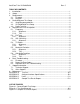
AutoTune™ for VX-P820/P920 Rev. C TABLE OF CONTENTS 1. Introduction .............................................................................................................. 1 2. Scope....................................................................................................................... 1 3. Requirements........................................................................................................... 2 3.1. Firmware ............................................................
AutoTune™ for VX-P820/P920 Rev. C LIST OF TABLES Table 4-1. Radio Test Setup Connections....................................................................... 2 Table 5-1. Test Channel Configuration............................................................................ 2 Table 5-2. Analyzer Configuration for Frequency Alignment and Test ............................ 2 Table 5-3. Frequency Alignment Results ........................................................................ 2 Table 5-4.
AutoTune™ for VX-P820/P920 Rev. C 1. Introduction The Vertex Standard VX-P820/P920 are VHF/UHF P25 portable radios providing analog FM and digital P25 reception and transmission of voice and data in the VHF/UHF frequency bands used in land mobile environments. The General Dynamics AutoTune™ application is designed to provide an automated test and alignment solution for Vertex Standard VX-P820/P920 radios. AutoTune™ supports the R2600 family of Communications Systems Analyzer. 2.
AutoTune™ for VX-P820/P920 Rev. C 3. Requirements 3.1. Firmware Before attempting to align or test a VX-P820/P920 radio, the radio’s firmware must be version 1.29 or later. This firmware version is required to support the AutoTune™ alignment and test capabilities. On models equipped with an LCD, the radio firmware version may be viewed by pressing and holding the side LAMP Button key while turning the radio on. After radio power-on and self test, the radio will enter the screen test/version view mode.
AutoTune™ for VX-P820/P920 Rev. C Software issues in some previous versions of the PROJ 25/ASTRO/SNET firmware may prevent correct monitor frequency configuration. Please refer to the analyzer’s Operator’s Manual for information on how to upgrade the analyzer firmware if necessary.
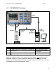
AutoTune™ for VX-P820/P920 Rev. C 4. Radio Alignment Test Setup In order to perform the alignment procedures, the VX-P820/P920 must be connected to both the PC and the communications analyzer as shown in the figure(s) below. Please make certain that the radio under test is configured as described in Figure 4-1 before attempting to perform the indicated alignment or test. Failure to do so may result in poor radio performance and/or damage to the communications analyzer or radio equipment under test. 4.1.
AutoTune™ for VX-P820/P920 4.2. Rev. C VX-P820/P920 Test Setup Figure 4-1. General Radio Test Setup Cable 1 2 3 Connections VX-P820/P920 Antenna port to R2670 RF IN/OUT port PC COM port OR USB to Serial Adapter to VX-P820/P920 Accessory Port PC COM port OR USB to Serial Adapter to R2670 RS-232 Port Table 4-1. Radio Test Setup Connections. Cable Description Coaxial BNC Cable Vertex Standard Part Number CT-109 and (optional) USB to Serial adapter. See APPENDIX B.
AutoTune™ for VX-P820/P920 4.3. Rev. C Radio Test Set A radio test set is a service aid which provides a means of injecting signals into and sampling audio output from a radio under test for purposes of performance verification. It generally connects to the radio’s universal/accessory port, to a PC, and to other test equipment, such as the R2670. For example, to determine the radio receiver’s sensitivity to incoming signals, a SINAD test may be performed.
AutoTune™ for VX-P820/P920 Rev. C 5. Alignment and Test Descriptions Table 5-1 provides the channel configuration for each Test Channel referenced throughout this section. Note that to find the channel operating frequency for a particular radio, the radio operating band must be known. The band designation can usually be located on a sticker underneath the radio’s battery. Band Signaling 485.1MHz Channel Space Wide Center --- 380.1MHz 450.1MHz Wide Low --- 469.9MHz 449.9MHz 519.
AutoTune™ for VX-P820/P920 Rev. C The following radio test report results are returned for the Frequency alignment: Name Result Description Pass or Fail. This indicates whether the alignment succeeded in bringing the radio parameter into alignment limits as specified in the limits file. Frequency Band center frequency for the radio under test. Max Limit Maximum passable frequency error, inclusive, as specified in the limits file.
AutoTune™ for VX-P820/P920 Rev. C values for the respective portions of the band. These softpot values are then programmed into the radio. Each configured channel’s RX Tune value is then updated to reflect these new radio softpot values. The following radio test report results are returned for the RX Tune alignment: Name Description Result Pass or Fail. This indicates whether the alignment succeeded. Frequency Band Center frequency for the radio under test.
AutoTune™ for VX-P820/P920 Rev. C Table 5-8. SQL Sensitivity Alignment Results 5.4. TX Power Monitor Mode RF Control Port Frequency Modulation Standard Monitor RF I/O Test Channel 06 FM Table 5-9. Analyzer Configuration for TX Power Alignment and Test 5.4.1. Attenuation 20 dB Alignment The radio is set to Test Channel 6 and commanded to transmit by the software.
AutoTune™ for VX-P820/P920 Rev. C Frequency Band center frequency for the radio under test. Max Limit Maximum passable power, inclusive, as specified in the limits file. Power Measured power after alignment. Min Limit Minimum passable power, inclusive, as specified in the limits file. Softpot Current radio parameter softpot value. Table 5-11. TX Power Test Results. 5.5.
AutoTune™ for VX-P820/P920 Rev. C described in APPENDIX C, the test is marked as pass. Otherwise, the test is marked as fail. The following radio test report results are returned for the Maximum Deviation test: Name Result Description Pass or Fail. This indicates whether the alignment succeeded in bringing the radio parameter into alignment limits as specified in the limits file. Name Maximum Deviation point under test. Frequency Band center frequency for the radio under test.
AutoTune™ for VX-P820/P920 Rev. C Table 5-16. Sub Audio Deviation Alignment Results. 5.6.2. Test The radio is set to Test Channel 4 and commanded to transmit by the software. The analyzer then samples the radio’s sub audio deviation. If the sampled deviation falls within the Sub Audio Deviation test limit range for the deviation point under test as described in APPENDIX C, the test is marked as pass. Otherwise, the test is marked as fail.
AutoTune™ for VX-P820/P920 Rev. C 6. Basic Troubleshooting 6.1. Firmware The radio firmware must be version 1.29 or later to be tested or aligned by the AutoTune software. Symptom AutoTune software fails to put radio into test mode. Possible Cause Incompatible radio firmware. Solution Before beginning a test or alignment, the radio under test must be placed into test mode. Successful entry into test mode can be observed on LCDequipped models when “AUTO TEST” is displayed on the radio’s LCD screen.
AutoTune™ for VX-P820/P920 Test or Alignment failure Analyzer measurement. Maximum Deviation test or alignment fails repeatedly Mistuned Modulation Balance parameter Radio left in AutoTest mode Radio communication after test or alignment. error. Table 6-3. Alignment and Test Troubleshooting Chart. Rev. C alignment to alignment. This variance does not affect the radio’s sensitivity in any way. Occasionally, an alignment or test may fail because a poor measurement was received from the analyzer.
AutoTune™ for VX-P820/P920 Rev. C 7. Support Information 7.1. Technical Support Telephone: 480.441.0664 Fax: 480.441.4535 Email: CTE@gdsatcom.com 7.2. Sales Support Telephone: 903-381-4131 Fax: 903-295-1479 Mobile: 847-878-2274 Email: CTE@gdsatcom.
AutoTune™ for VX-P820/P920 Rev. C 8. References VX-P920 Series UHF Band Service Manual. Part# EC033U95A. Cypress, CA: Vertex Standard CO., LTD., 2005. VX-P920 Series VHF Band Service Manual. Part# EC033N95A. Cypress, CA: Vertex Standard CO., LTD., 2005.
AutoTune™ for VX-P820/P920 APPENDIX A. Rev. C Test Set The figure below depicts the test set schematic necessary to perform several manual VX-P820/P920 receiver alignments and tests. This schematic is provided courtesy of Vertex Standard USA, Inc. Figure A-1. Test Set Schematic Source: EC033U95A, VX-P920 Series UHF Band Service Manual, ©2005, Vertex Standard CO., LTD.
AutoTune™ for VX-P820/P920 APPENDIX B. DB-25 (M) Analyzer Rev. C Analyzer Interface Specifications Cable Wiring DB-9 (F) Computer TxD 2 2 RxD RxD 3 3 TxD RTS 4 7 RTS CTS DSR 5 6 4 DTR DCD 8 1 DCD 20 8 6 CTS DSR 7 5 GND DTR GND Table B-1.
AutoTune™ for VX-P820/P920 APPENDIX C. Rev. B Limits The limits used to determine whether a test or alignment passes or fails are stored in Vertex Standard.VXP820/P920.Limits.ini. This file contains the default limits as defined by the radio manufacturer and generally should not be modified.
AutoTune™ for VX-P820/P920 Rev. B Section Name 5.1 Frequency +/- 300 Hz 5.2 RX Tune -103 dBm 5.3 SQL Sensitivity 5.4 5.5 5.
AutoTune™ for VX-P820/P920 Section Name 5.1 Frequency 5.2 RX Tune 5.3 SQL Sensitivity 5.4 5.5 5.6 TX Power Maximum Deviation Sub Audio Deviation Rev. B Point VHF UHF A (G6) UHF H (G8) UHF D (G7) 0 Hz -103 dBm TI NSQ Wide -116 dBm TH NSQ W -122 dBm RSSI SQL W -114 dBm TX SAVE W -98 dBm TI NSQ N -116 dBm TH NSQ N -121 dBm RSSI SQL N -114 dBm TX SAVE N -98 dBm High 5.0 W Low-High 2.5 W Low-Mid 1.0 W E-Low 0.25 W Wide 4.2 kHz Narrow 2.1 kHz Digital 3.
AutoTune™ for VX-P820/P920 Section Name 5.1 Frequency 5.2 RX Tune 5.3 SQL Sensitivity 5.4 5.5 5.6 TX Power Maximum Deviation Sub Audio Deviation Rev.
AutoTune™ for VX-P820/P920 Section Name 5.1 Frequency 5.2 RX Tune 5.3 SQL Sensitivity 5.4 5.5 5.6 TX Power Maximum Deviation Sub Audio Deviation Rev.
AutoTune™ for VX-P820/P920 APPENDIX D. Rev. B Sample Test Result Report Figure D-1.