
User`s guide


AutoTune™ for VX-P820/P920 Rev. C
7
5. Alignment and Test Descriptions
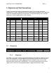
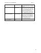
Table 5-1 provides the channel configuration for each Test Channel referenced
throughout this section. Note that to find the channel operating frequency for a particular
radio, the radio operating band must be known. The band designation can usually be
located on a sticker underneath the radio’s battery.
VHF UHF-A (G6) UHF-H (G8) UHF-D (G7)
Channel
Space
Band Signaling
CH 01
154.1MHz 435.1MHz 415.1MHz 485.1MHz Wide Center ---
CH 02
134.1MHz 400.1MHz 380.1MHz 450.1MHz Wide Low ---
CH 03
173.9MHz 469.9MHz 449.9MHz 519.9MHz Wide High ---
CH 04
154.1MHz 435.1MHz 415.1MHz 485.1MHz Wide Center CTCSS
CH 05
154.1MHz 435.1MHz 415.1MHz 485.1MHz Wide Center DCS
CH 06
154.1MHz 435.1MHz 415.1MHz 485.1MHz Narrow Center ---
CH 07
154.1MHz 435.1MHz 415.1MHz 485.1MHz Narrow Center CTCSS
CH 08
154.1MHz 435.1MHz 415.1MHz 485.1MHz Narrow Center DCS
CH 09
154.1MHz 435.1MHz 415.1MHz 485.1MHz Digital Center Digital
Table 5-1. Test Channel Configuration
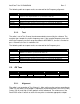
5.1. Frequency
Monitor Mode RF Control Port Frequency Modulation Attenuation
Standard Monitor RF I/O Test Channel 06 FM 20 dB
Table 5-2. Analyzer Configuration for Frequency Alignment and Test
5.1.1. Alignment
The radio is set to Test Channel 6 and commanded to transmit by the software. Using a
best linear fit algorithm, several frequency error samples are taken with the analyzer
and used to determine the radio softpot value with a frequency error closest to the
alignment target value found in APPENDIX C. Once the measurement closest to the
target value is found, the corresponding softpot is programmed into the radio.