
User`s guide


AutoTune™ for VX-P820/P920 Rev. C
5
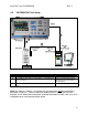
4.2. VX-P820/P920 Test Setup
Figure 4-1. General Radio Test Setup
Cable Connections Cable Description
1 VX-P820/P920 Antenna port to R2670 RF IN/OUT port Coaxial BNC Cable
2 PC COM port OR USB to Serial Adapter to VX-P820/P920
Accessory Port
Vertex Standard Part Number
CT-109 and (optional) USB to
Serial adapter.
3 PC COM port OR USB to Serial Adapter to R2670 RS-232
Port
See APPENDIX B.
Table 4-1. Radio Test Setup Connections.
Note: For Cable 2 in Table 4-1, the Accessory Port connector must be configured as
described in Figure 4-1, with the cable wire leading to the PC pointing in the same
direction as the radio antenna connector. Incorrect orientation of Cable 2 will result in no
radio power-up or radio communication failure.